Tuesday, April 30, 2013

Dual Opamp Buffered Power Supply

Dual Opamp Buffered Power SupplyThere will be instances where the currents from each supply will be unequal. Where this is the case, the resistor divider is not sufficient, and the +ve and -ve voltages will be unequal. By using a cheap opamp (such as a uA741), a DC imbalance between supplies of up to about 15mA will not cause a problem. However, we can do better with a dual opamp (which will cost the same or less anyway), and increase the capability for up to about 30mA of difference between the two supplies.

Author: http://sound.westhost.com/project43.htm
[Continue reading...]

Sunday, April 21, 2013

LED FLASHER WITH ONE TRANSISTOR


This is a unique flasher circuit employing a single driver transistor that takes its flash-rate from a flashing LED. The flasher within the photo is 3mm. An ordinary LED wont work. The flash rate can not be altered by the brightness of the high-bright white LED will be adjusted by altering the 1k resistor across the 100u electrolytic to 4k7 or 10k. The 1k resistor discharges the 100u in order that when the transistor activates, the charging current into the 100u illuminates the white

LED.
If a 10k discharge resistor is used, the 100u isnt absolutely discharged and therefore the LED doesnt flash as bright. All the components within the photo are within the same places as within the circuit diagram to make it simple to envision how the components are connected.

The circuit uses a flashing LED to flash a super-bright 20,000mcd white LED

[Continue reading...]

Vocal Adaptor for Bass Guitar Amp

These days, music is a major hobby for the young and not-so-young. Lots of people  enjoy  making  music,  and  more  and  more dream of showing off their talents on stage. But one of the major problems often encountered is the cost of musical equipment. How many amateur music groups sing  through an amp borrowed from a guitarist or bass player?
This is where the technical problems arise not in terms of the .25” (6.3 mm)  jack, but in terms of the sound quality (the words  are barely understandable) and volume (the amp  seems to produce fewer decibels than for a guitar). What’s more, unpredictable feedback may cause damage to the speakers and is very unpleasant on the ear. This cheap little  easy-to-build project can help solve these technical  problems.
Circuit diagram :
Vocal Adaptor for Bass-Guitar Amp-Circuit Diagram
A guitar (or bass guitar) amplifier is designed first and foremost to reproduce the sound of the guitar or bass as faithfully as  possible. The frequency response of the amp doesn’t need to be as wide or as flat as in hi-fi (particularly at the high end), and so this sort of amplifier won’t permit faithful reproduction of the voice. If you build an adaptor to compensate for the amp’s limited frequency response by amplifying in advance the frequencies that are  then attenuated by the amp, it’s possible to  improve the quality of the vocal sound. That’s  just what this circuit attempts to do.
The adaptor is built around the TL072CN low-noise dual FET op-amp, which offers good value for money. The NE5532 can be used with almost the same sound quality, but at (slightly) higher cost. The circuit breaks  down into two stages. The first stage is used to match the input impedance and amplify the microphone signal. For a small 15 W guitar or bass amplifier, the achievable gain is  about 100 (gain = P1/R1). For more powerful amplifiers, the gain can be reduced to  around 50 by adjusting P1. The second stage amplifies the band of frequencies (adjustable using P2 and P3) that are attenuated by the guitar amp, so as to be able to reproduce the (lead)  singer ’s voice as clearly, distinctly, and  accurately as possible. To refine the adaptor and tailor it to your amplifier and speaker, don’t be afraid to experiment with the component values and the type  of capacitors.
The circuit can readily be powered using a 9 V battery, thanks to the voltage divider R4/R5 which converts it into a symmetrical  ±4.5 V supply.

Author : Jérémie Hinterreiter
[Continue reading...]

Saturday, April 13, 2013

Tandem Doorbell

The creator had a problem: the neighbours  had exactly the same kind of doorbell as he did (actually a 50 Hz buzzer), so it used to ben’t always clear who wanted to reply to the door. To keep away from confusion, the writer augmented the present doorbell with a wireless edition a fairly cheaper possibility at current  costs. All that was essential for this was once to organize for the present button and wiring to additionally actuate the wireless doorbell. 

Circuit diagram :

Tandem Doorbell Circuit Diagram

The author unfolded the button enclosure of the wireless doorbell and used a multi-meter to search out out which set of contacts were closed when the button was pressed. This is the place the relay output should be linked (see the schematic diagram). The circuit is just about self-explanatory: when the prevailing doorbell button is pressed to actuate the  buzzer, the voltage is rectified through the bridge rectifier and controlled at 5 V through the 7805. This voltage powers the relay in an instant, causing the switch within the wireless doorbell button to be shorted. As a result, together with the buzzer a  huge Big Ben chime indicates that some-one is on the door. Now the writer simply hopes that hellos neighbour doesn’t replica his concept.


http://www.ecircuitslab.com/2012/05/tandem-doorbell.html
[Continue reading...]

Maximum Minimum Voltage Indicator

This\r\n circuit indicates which of three voltages in the vary from about about\r\n -4V to about +4V - at A, B and C - is the very best by way of lights one in all \r\nthree indicator LEDs. Alternatively, it may be wired to point the \r\nlowest of three voltages or to indicate both the easiest and lowest \r\nvoltages. Op amps IC1a, IC1b & IC1c are wired as comparators, while \r\nthe three indicator LEDs and their series 1kO present limiting resistors\r\n are strung across the op amp outputs to put in force the proper logic\r\n operates.

Circuit diagram:
 Maximum Minimum Voltage Indicator Circuit Diagram

For\r\n instance, LED A will gentle only when pin eight of IC1c is low (ie, A larger\r\n B) and pin 7 of IC1b is excessive (ie, A higher C). Similarly, LED B will \r\nlight only when pin 8 of IC1c is high (ie, B larger A) and pin 1 of \r\nIC1a is low (ie, B better C). LED C works in identical fashion if the \r\nvoltage at C is the very best. Note that if the entire LEDs and their \r\nparallel 1N4148 diodes are reversed, the circuit will indicate the \r\nlowest of the three enter voltages. And if each and each 1N4148 diode is replaced\r\n through a LED, the circuit will indicate each the perfect and lowest enters.

Author: Andrew Partridge - Copyright: Silicon Chip
[Continue reading...]

Type of UPS Uninterruptible Power Supply

UPS design of the model is divided into several types that produce different performance characteristics:
A. Standby
2. Line Interactive
3. Double Conversion On-Line
4. Delta Conversion On-Line
Standby UPS types
This type is commonly used by home users for the Presidency with their PC. UPS to be able to do this type of filtration against power failures and flow management, in addition to design efficient, small size and inexpensive.

Line Interactive UPS types
Type of UPS | Uninterruptible Power Supply UPS is the type most often used in small business unit, web developer, and a number of servers located in government departments. Because, in addition to having high levels of reliability, this type also have the ability to adjust the voltage that is sufficient
fine.
UPS has an inverter is always connected to the output of the UPS system to convert the power from batteries into AC. In normal circumstances, the Inverter will perform battery charging. While in a state of power outages, Transfer Switch will close and drain power from the batteries to the UPS output. Position that is always connected to the inverter output filter provides additional power. This makes the type of UPS is widely used for server and electrical conditions are not too good.

Double Conversion type UPS On-Line
This type is most common for UPS with power more than 10kVA. These types have in common with the type of Standby. Only this type has a power source located on the inverter, not the AC power source. In this type, the main electricity supply interruption will not trigger a transfer switch for the incoming AC power to the central input to charge the batteries that provide power to the Inverter located at the output. Therefore, when the AC power is disconnected, the flow of energy will be transferred immediately without taking a break when the transfer occurs. This type of UPS above shows the performance of the average. Can be said of this type of approach the ideal of a UPS, unfortunately this type of heat is high enough.

UPS type Delta Conversion On-Line
Almost the same as the Double Conversion type, type Delta used to always supply voltage Inverter. When the power supply is interrupted, this type do the same with Double Conversion type. Delta Conversion has two functions, the first is to control the input power characteristics. While the second function is to control the input current to direct the process of charging the battery system. The thing to remember is to minimize this type of energy is wasted. In addition, it has a high compatibility to various types of generators and reduce the need for the use of cables.
[Continue reading...]

Friday, April 12, 2013

Step Up Booster Powers Eight White LEDs

Tiny white LEDs are capable of delivering ample white light without the fragility problems and costs associated with fluorescent backlights. They do pose a problem however in that their forward voltage can be as high as 4 V, precluding them being from powered directly from a single Li-Ion cell. Applications requiring more white LEDs or higher efficiency can use an LT1615 boost converter to drive a series connected array of LEDs. The high efficiency circuit (about 80%) shown here can provide a constant-current drive for up to eight LEDs. Driving eight white LEDs in series requires at least 29 V at the output and this is possible thanks to the internal 36-V, 350-mA switch in the LT1615.

The constant-current design of the circuit guarantees a steady current through all LEDs, regardless of the forward voltage differences between them. Although this circuit was designed to operate from a single Li-Ion battery (2.5V to 4.5V), the LT1615 is also capable of operating from inputs as low as 1 V with relevant output power reductions. The Motorola MBR0520 surface mount Schottky diode (0.5 A 20 V) is a good choice for D1 if the output voltage does not exceed 20 V. In this application however, it is better to use a diode that can withstand higher voltages like the MBR0540 (0.5 A, 40 V). Schottky diodes, with their low forward voltage drop and fast switching speed, are the best match.

Many different manufacturers make equivalent parts, but make sure that the component is rated to handle at least 0.35 A. Inductor L1, a 4.7-µH choke, is available from Murata, Sumida, Coilcraft, etc. In order to maintain the constant off-time (0.4 ms) control scheme of the LT1615, the on-chip power switch is turned off only after the 350-mA (or 100-mA for the LT1615-1) current limit is reached. There is a 100-ns delay between the time when the current limit is reached and when the switch actually turns off. During this delay, the inductor current exceeds the current limit by a small amount. This current overshoot can be beneficial as it helps increase the amount of available output current for smaller inductor values.


This will be the peak current passed by the inductor (and the diode) during normal operation. Although it is internally current-limited to 350 mA, the power switch of the LT1615 can handle larger currents without problems, but the overall efficiency will suffer. Best results will be o btained when IPEAK is kept well below 700 mA for the LT1615.The LT1615 uses a constant off-time control scheme to provide high efficiencies over a wide range of output current. The LT1615 also contains circuitry to provide protection during start-up and under short-circuit conditions.

When the FB pin voltage is at less than approximately 600 mV, the switch off-time is increased to 1.5 ms and the current limit is reduced to around 250 mA (i.e., 70% of its normal value). This reduces the average inductor current and helps minimize the power dissipation in the LT1615 power switch and in the external inductor L1 and diode D1. The output current is determined by Vref/R1, in this case, 1.23V/68 = 18 mA). Further information on the LT1615 may be found in the device datasheets which may be downloaded from www.linear-tech.com/pdf/16151fa.pdf
 
 
Streampowers
[Continue reading...]

Simple Bass Treble Tone Control

The LM1036 is a DC keep watch overled tone (bass/treble), quantity and balance circuit for stereo utilitys in automotive radio, TV and audio methods. An extra keep watch over enter permits loudness compensation to be merely effected. Four keep watch over enters present keep watch over of the bass, treble, balance and extent operates thru application of DC voltages from a faraway keep watch over device or, however, from four potentiometers which is also biased from a zener regulated provide provided on the circuit.
Circuit diagram :
\"bass-treble-tone-control-circuit\"
Bass Treble Tone Control Circuit Diagram

Each tone response is outlined by means of a single capacitor chosen to offer the specified attribute.
Features:
  • Wide supply voltage range, 9V to 16V
  • Large volume keep an eye fixed on vary, seventy five dB typical
  • Tone regulate, ±15 dB typical
  • Channel separation, 75 dB typical
  • Low distortion, 0.06% typical for an enter degree of zero.3 Vrms
  • High signal to noise, 80 dB standard for an input stage of 0.3 Vrms
  • Few exterior parts required
Note:
Vcc can additionally be anything between 9V to 16V and the output capacitors are 10uF/25V electrolytic
[Continue reading...]

Build LED Light Pen Schematic

Physicians and repair engineers often use small light pens for visual examination purposes. Rugged and expensive as these pens may be, their weak point is the bulb, which is a ‘serviceable’ part. In practice, that nearly always equates to ‘expensive’ and / or ‘impossible to find’ when you need one.

LEDs have a much longer life than bulbs and the latest ultra bright white ones also offer higher energy-to-light conversion efficiency. On the down side, LEDs require a small electronic helper circuit called ‘constant-current source’ to get the most out of them.
 
LED Light Pen Circuit Diagram
LED-Light-Pen-Circuit-Diagram

Here, T1 and R1 switch on the LED. R2 acts as a current sensor with T2 shunting off (most of) T1’s base bias current when the voltage developed across R2 exceeds about 0.65 V. The constant current through the white LED is calculated from

R2 = 0.65 / ILED
With some skill the complete circuit can be built such that its size is equal to an AA battery. The four button cells take the place of the other AA battery that used to be inside the light pen. Link


Author: Myo Min – Copyright: Elektor
[Continue reading...]

1996 Chevrolet Camaro Z28 Wiring Diagram

1996 Chevrolet Camaro Z28 Wiring Diagram

The Part of 1996 Chevrolet Camaro Z28 Wiring Diagram: instrument cluster, tachometer, black wire, yellow wire, red wire, crankshaft, power distribution,camshaft position sensor, tachometer output, sensor ground, sensor ignition positive voltage, tachometer output, reference sigal, knock sensor, srankshaft position sensor, underhood electrical center, sensor ignition positive voltage, bypass control, powertrain control module.
[Continue reading...]

Simple Remote Doorbell Warning Switch Circuit

This circuit should only be used with the solenoid type chime doorbells, the electronic type that play tunes will not work here. This is the simple circuit design.


The basic principle work is the hardest part for this circuit was the title. It is quite easy to miss the sound of a doorbell if you are watching the television, this circuit gets round the problem by providing a visual indication, i.e. a lamp. As an alternative, a LED could also be used. You could just parallel a lamp across the doorbell, but this would mean extra drain from the doorbell batteries or transformer.

Using a series resistor R1 actually reduces current flow, and if run from batteries, will give them a longer life. The value of R1 is chosen so that about 0.6 to 0.7 volts is dropped across it, and the doorbell should still ring. I used a combination of a 22 ohm resistor in parallel with a 50 ohm. The doorbell still rang and circuit operated correctly. I used to have an electromechanical counter that registered each time when someone pressed the switch.
[Continue reading...]

Thursday, April 11, 2013

Little Door Guard

If some intruder tries to open the door of your house, this circuit sounds an alarm to alert you against the attempted intrusion. The circuit (Fig. 1) uses readily available, low-cost components. For compactness, an alkaline 12V battery is used for powering the unit. Input DC supply is further regulated to a steady DC voltage of 5V by 3-pin regulator IC 7805 (IC2).

Fig. 1: Circuit of the door guard


Circuit of the door guard


Assemble the unit on a general-purpose PCB as shown in Fig. 4 and mount the same on the door as shown in Fig. 3. Now mount a piece of mirror on the door frame such that it is exactly aligned with the unit. Pin configurations of IC UM3561 and transistors 2N5777 and BC547 are shown in Fig. 2.

Fig. 2: Pin configurations of UM3561 and transistors 2N5777 and BC547

UM3561 and transistors


Initially, when the door is closed, the infrared (IR) beam transmitted by IR LED1 is reflected (by the mirror) back to phototransistor 2N5777 (T1). The IR beam falling on phototransistor T1 reverse biases npn transistor T2 and IC1 does not get positive supply at its pin 5. As a result, no tone is produced at its output pin 3 and the loudspeaker remains silent. Resistor R1 limits the operating current for the IR LED.
When the door isopened, the absence of IR rays at phototransistor T1 forward biases npn transistor T2, which provides supply to  positiveIC1. Now 3-sirensound generator IC UM3561 (IC1) gets power via resistor R5. The output of IC1 at pin 3 is amplified by Darlington-pair transistors T3 and T4 to produce the alert tone via the loudspeaker.

Fig. 3: Back view of the door assembly

Back view of the door assembly

Rotary switch S2 is used to select the three preprogrammed tones of IC1. IC1 produces fire engine, police and ambulance siren sounds when its pin 6 is connected to point F, P or A, respectively.

Suggested enclosure
Fig. 4: Suggested enclosure with major components layout


Source: http://www.ecircuitslab.com/2012/06/little-door-guard.html
[Continue reading...]

Mobile Car Stereo Player

Using a mobile phone while driving is dangerous. It is also against the law. However, you can use your mobile phone as a powerful music player with the help of a stereo power amplifier. This does away with the need of a sophisticated in-dash car music system. Most mobile phones have a music player that offers a number of features including preset/manual sound equalisers. They have standard 3.5mm stereo sockets that allow music to be played through standard stereo headphones/sound amplifiers. Nokia 2700 classic is an example.

Mobile Car Stereo Player Circuit Diagram

Circuit of mobile car stereo player

A car audio amplifier with 3.5mm socket can be designed and simply connected to the mobile phone output via a shielded cable with suitable connectors/jacks (readymade 3.5mm male-to-male connector cable is a good alternative). Fig. 1 shows the circuit of car stereo player. It is built around popular single-chip audio power amplifier TDA1554Q (IC1). The TDA1554Q is an integrated class-B power amplifier in a 17-lead single-in-line (SIL) plastic power package.

IC TDA1554Q contains four 11W identical amplifiers with differential input stages (two inverting and two non-inverting) and can be used for single-ended or bridge applications. The gain of each amplifier is fixed at 20 dB. Here it is configured as two 22W stereo bridge amplifiers. The amplifier is powered from the 12V car battery through RCA socket J2. Diode D1 protects against wrong-polarity connection. LED1 indicates the power status.

Stereo Jack :
3.5mm stereo socket and (b) 3.5mm

(a) 3.5mm stereo socket and (b) 3.5mm Stereo Jack

Connect stereo sound signal from the 3.5mm headset socket of the mobile phone to audio input socket J1. When you play the music from your mobile, IC1 amplifies the input. The output of IC1 is fed to speakers LS1 and LS2 fitted at a suitable place in your car. Electrolytic capacitor C5 connected between pin 4 of IC1 and GND improves the supply-voltage ripple rejection. Components R2 and C4 connected at mute/standby pin (pin 14) of IC1 eliminate the switch on/off plop. The circuit is quite compact. A good-quality heat-sink assembly is crucial for IC1. Fig. 2 shows the stereo socket and stereo jack.

Proposed enclosure
Proposed enclosure

Assemble the circuit on a general-purpose PCB and enclose in a suitable cabinet. Small dimensions of the power amplifier make it suitable for being enclosed in a plastic (ABS) case with vent holes. Signal input socket, speaker output terminals, on/off switch, indicator, fuse holder and power supply socket are best located on the front panel of the enclosure as shown in Fig. 3.

Source : http://www.ecircuitslab.com/2012/04/mobile-car-stereo-player.html
[Continue reading...]

Mini High Voltage Generator Circuit

Here’s a project that could be useful this summer on the beach, to stop anyone touching your things left on your beach towel while you’ve gone swimming; you might equally well use it at the office or workshop when you go back to work. In a very small space, and powered by simple primary cells or rechargeable batteries, the proposed circuit generates a low-energy, high voltage of the order of around 200 to 400 V, harmless to humans, of course, but still able to give a quite nasty ‘poke’ to anyone who touches it.

Quite apart from this practical aspect, this project will also prove instructional for younger hobbyists, enabling them to discover a circuit that all the ‘oldies’ who’ve worked in radio, and having enjoyed valve technology in particular, are bound to be familiar with. As the circuit diagram shows, the project is extremely simple, as it contains only a single active element, and then it’s only a fairly ordinary transistor. As shown here, it operates as a low-frequency oscillator, making it possible to convert the battery’s DC voltage into an AC voltage that can be stepped up via the transformer.

Using a centre-tapped transformer as here makes it possible to build a ‘Hartley’ oscillator around transistor T1, which as we have indicated above was used a great deal in radio in that distant era when valves reigned supreme and these was no sign of silicon taking over and turning most electronics into ‘solid state’. The ‘Hartley’ is one of a number of L-C oscillator designs that made it to eternal fame and was named after its invertor, Ralph V.L Hartley (1888-1970). For such an oscillator to work and produce a proper sinewave output, the position of the intermediate tap on the winding used had to be carefully chosen to ensure the proper step-down (voltage reduction) ratio.

Here the step-down is obtained inductively. Here, optimum inductive tapping is not possible since we are using a standard, off-the-shelf transformer. However we’re in luck — as its position in the centre of the winding creates too much feedback, it ensures that the oscillator will always start reliably. However, the excess feedback means that it doesn’t generate sinewaves; indeed, far from it. But that’s not important for this sort of application, and the transformer copes very well with it.

The output voltage may be used directly, via the two current-limiting resistors R2 an R3, which must not under any circum-stances be omitted or modified, as they are what make the circuit safe. You will then get around 200 V peak-to-peak, which is already quite unpleasant to touch. But you can also use a voltage doubler, shown at the bottom right of the figure, which will then produce around 300 V, even more unpleasant to touch. Here too of course, the resistors, now know as R4 and R5, must always be present. The circuit only consumes around a few tens of mA, regardless of whether it is ‘warding off’ someone or not! If you have to use it for long periods, we would however recommend powering it from AAA size Ni-MH batteries in groups of ten in a suitable holder, in order not to ruin you buying dry batteries.

Circuit diagram:
mini-high-voltage-generator-circuit

Warning!
If you build the version without the voltage doubler and measure the output voltage with your multimeter, you’ll see a lower value than stated. This is due to the fact that the waveform is a long way from being a sinewave, and multimeters have trouble interpreting its RMS (root-mean-square) value. However, if you have access to an oscilloscope capable of handling a few hundred volts on its input, you’ll be able to see the true values as stated. If you’re still not convinced, all you need do is touch the output terminals...

To use this project to protect the handle of your beach bag or your attachecase, for example, all you need do is fix to this two small metallic areas, quite close together, each connected to one output terminal of the circuit. Arrange them in such a way that unwanted hands are bound to touch both of them together; the result is guaranteed! Just take care to avoid getting caught in your own trap when you take your bag to turn the circuit off!
 
 
Source by : Streampowers
[Continue reading...]

Superstock Mechanics Workingthrust Reverser Regional

Aircraft Mechanic on Aircraft Mechanic
Aircraft Mechanic.


Aircraft Mechanic on Wren Aircraft Mechanic
Wren Aircraft Mechanic.


Aircraft Mechanic on Aircraft Mechanic Average Salaries   Ehow Com
Aircraft Mechanic Average Salaries Ehow Com.


Aircraft Mechanic on Aircraft Mechanic   On Duty   Military Life   Careers   Defence Forces
Aircraft Mechanic On Duty Military Life Careers Defence Forces.


Aircraft Mechanic on Superstock   Two Mechanics Working On A Thrust Reverser For A Regional
Superstock Two Mechanics Working On A Thrust Reverser For A Regional.


Aircraft Mechanic on Jet Aircraft Mechanic
Jet Aircraft Mechanic.


Aircraft Mechanic on Career Guide For Aircraft Mechanics   Learnthat Com   Free Tutorial
Career Guide For Aircraft Mechanics Learnthat Com Free Tutorial.


Aircraft Mechanic on What Does An Aircraft Mechanic Do
What Does An Aircraft Mechanic Do.


Aircraft Mechanic on Aircraft Mechanic
Aircraft Mechanic.


Aircraft Mechanic on Aircraft Mechanic Career Guide  Eskwelahan Com   Philippine Online
Aircraft Mechanic Career Guide Eskwelahan Com Philippine Online.


[Continue reading...]

Loudspeaker Protector Monitors Current

This circuit uses a 0.1O 1W resistor connected in series with the output of a power amplifier. When the amplifier is delivering 100W into an 8O load, the resistor will be dissipating 1.25W. The resulting temperature rise is sensed by a thermistor which is thermally bonded to the resistor. The thermistor is connected in series with a resistor string which is monitored by the non-inverting (+) inputs of four comparators in an LM339 quad comparator. All of the comparator inverting inputs are connected to an adjustable threshold voltage provided by trimpot VR1. As the thermistor heats up, its resistance increases, raising the voltage along the resistor ladder.

Circuit diagram:
loudspeaker-protector-circuit-diagram-monitors-current Loudspeaker Protector Circuit Diagram

When the voltage on the non-inverting input of each comparator exceeds the voltage at its inverting input, the output switches high and illuminates the relevant LED. NOR gate latches are connected to the outputs of the third and fourth comparators. When the third comparator switches high, the first latch is set, turning on Q1 and relay 1. This switches in an attenuation network (resistors RA & RB) to reduce the power level. However, if the power level is still excessive, comparator 4 will switch, setting its latch and turning on Q2 and relay 2.

This disconnects the loudspeaker load. The thermistor then needs to cool down before normal operation will be restored. The values of R1-R4 depend on the thermistor used. For example, if a thermistor with a resistance of 1.5kO at 25°C is used, then R1 could be around 1.5kO and R2, R3 and R4 would each be 100O (depending the temperature coefficient of the thermistor). The setup procedure involves connecting a sinewave oscillator to the input of the power amplifier and using a dummy load for the output. Set the power level desired and adjust trimpot VR1 to light LED1. Then increase the power to check that the other LEDs light at satisfactory levels.


Source by : Streampowers
[Continue reading...]

Wednesday, April 10, 2013

Voltage Tester for Model Batteries

With a suitable load, the terminal voltage of a NiCd or lithium-ion battery is proportional to the amount of stored energy. This relationship, which is linear over a wide range, can be used to build a simple battery capacity meter. 

Circuit Image :
 Voltage Tester for Model Batteries Image
Voltage Tester for Model Batteries Circuit Image 

This model battery tester has two functions: it provides a load for the battery, and at the same time it measures the terminal voltage. In addition, both functions can be switched on or off via a model remote-control receiver, to avoid draining the battery when it is not necessary to make a measurement. The load network, which consists of a BC517 Darlington transistor (T2) and load resistor R11 (15 Ω /5 W), is readily evident. When the load is active, the base of T1 lies practically at ground level. Consequently, T1 conducts and allows one of the LEDs to be illuminated. 

Circuit Diagram :
Voltage Tester for Model Batteries-Circuit Diagram
Voltage Tester for Model Batteries Circuit Diagram

The thoroughly familiar voltmeter circuit, which is based on the LM3914 LED driver, determines which LED is lit. The values of R6 and R7 depend on the type and number of cells in the battery. The objective here is not to measure the entire voltage range from 0 V, but rather to display the portion of the range between the fully charged voltage and the fully discharged voltage. Since a total of ten LEDs are used, the display is very precise. For a NiCd battery with four cells, the scale runs from 4.8 V to 5.5 V when R6 = R7 = 2 kΩ. The measurement scale for a lithium-ion battery with two cells ranges from 7.2 V to 8.0 V if R6 = 2 kΩ and R7 = 1 kΩ. 

For remote-control operation, both jumpers should be placed in the upper position (between pin 1 and the middle pin). In this configuration, either a positive or negative signal edge will start the measurement process. A positive edge triggers IC1a, whose output goes High and triggers IC1b. A negative edge has no effect on IC1a, but it triggers IC1b directly. In any case, the load will be activated for the duration of the pulse from monostable IC1b. Use P12 to set the pulse width of IC1a to an adequate value, taking care that it is shorter than the pulse width of IC1b. 

If the voltage tester is fitted into a remote-controlled model, you can replace the jumpers with simple wire bridges. However, if you want to use it for other purposes, such as measuring the amount of charge left in a video camera battery, it is recommended to connect double-throw push-button switches in place of JP1 and JP2. The normally closed contact corresponds to the upper jumper position,while the normally open contact corresponds to the lower position.

Parts :
Resistors:
R1,R2 = 47kΩ
R3 = 100kΩ
R4 = 500kΩ
R5 = 1kΩ
R6,R7 = see text (1% resistors!)
R8 = 1kΩ5
R9 = 1kΩ2
R10 = 330Ω
R11 = 15Ω 5W
R12 = 15kΩ
P1 = 100kΩ preset
Capacitors:
C1 = 10nF
C2 = 100nF
Semiconductors:
D1-D10 = LED, red, high effi-ciency
T1 = BC557
T2 = BC517
IC1 = 74HC123
IC2 = LM3914AN
Miscellaneous:
PC1,PC2,PC3 = solder pin
JP1,JP2 = jumper or pushbutton

PCB Layout :
B. PCB Laout
Voltage Tester for Model Batteries PCB Layout
 
 
Streampowers
[Continue reading...]

With Auto Sound Systems Newest Technology isnt Necessarily Greatest Technology

We live in a world where music is our constant companion. We take it with us to the beach, to work, to exercise, even while riding bikes or talking on our cell phones. It only makes sense that in our cars we would like to have the best possible auto sound systems our hard earned dollars can buy. The problem is that new technology is being introduced to the market each and every day and many of us feel as though if we hold our breath just a little bit longer something even better and more spectacular will come along. We know that we will absolutely want to kick ourselves if we buy in to "this or that" companys auto sound system that was phenomenal yesterday, just before the next great thing hits the market.


The truth is that superior auto sound system technology exists already and the question isnt if it will hit the market but rather when. And when seems to be a pretty big question when it comes to emerging technologies. There are always so many things that control when the actual product will hit the shelves in stores or even how much supply will be available at that point in time. The really good news for consumers is that if you wait until that point, chances are the prices on the system you like now will probably lower significantly almost overnight.

While the geek in me would love to have the latest and greatest of gadgets at all times, the mom in me knows that the kids will need braces, new shoes for soccer, and (eventually) college tuition. For those reasons, I will continue typing on my sadly outdated eMachine and secretly long for the brand new Dell notebook while listening to the latest tunes on my iPod Shuffle while secretly longing for one of the new iPods, which is capable of playing video. I will live however, and will enjoy watching others play with their new gadget goodies while I learn about them and wait for the prices to drop (just like DVD players a few years back).

I am at least intelligent enough to realize that most of the time it is best not to be the first to buy a new product or an emerging technology. Let someone else take the risks associated with buying an essentially untried product while I sit back and listen to what they have to say. This way I can make an informed decision without bearing the scars associated with testing an untried product.

There are many things Im willing to sacrifice and many more things I give to my children as guinea pigs. The thing I have noticed quite often with them is that if it can survive a few weeks in their care, it is a pretty safe bet and might even be worth purchasing stock in the company. We all have some things that are more important to us than others and while I love technology there are other things I love more.

Music, however, is a very important part of my life and I do try to keep current with the latest and greatest when it comes to auto sound systems. My favorite at the moment is the Bose. Every piece of this equipment is designed with the idea of making music sound, as it should. You can get the biggest and greatest sound quality from this system without giving up half your trunk or your entire back seat. Bose is one of the more expensive products on the market when it comes to auto sound systems but it is well worth every penny.

When checking out your options for an auto sound system be sure to keep in mind that the most expensive product is not necessarily the best product-no matter what the salesman tells you. By learning as much as possible about all choices you may find that one of the less expensive systems is actually better suited for your auto sound system needs.

[Continue reading...]

Let’s to build a mini organ keyboard circuit using UM3511

The previous
day my son said ” A friend has a mini organ. Casio SA-76 44 Key Mini
Keyboard, Orange It is Good quality but expensive.
My son would have
the same. But I said, as we are the Electronic inventor, to try to
create their own. We are proud and cheaper too.
You might like this
mini organ keyboard circuit certainly. Because in addition to the
simple, the price is not expensive, effective really worthwhile.
You may consider the main features of the circuit, as follows.
1. Can works with DC voltage in rang 3-12 Volt by low current consumption.
2. There are the music playback up to 15 keys, or a note from G3-G5.
3. Can be programmed to play. Repeat for up to 47 notes.
4. Can act as a music source by up to 15 songs.(Simple carbohydrates. Press any key. To select the desired song.)
How circuit works
In the heart of the circuit is the UM3511
-IC is designed to act this purpose

-Internal IC consists of a lot. We do not need to explain the
operation of the circuit Internal this IC. Our job only assembly
equipment used in the first the circuit to be completed.
let-s-to-build-a-mini-organ-keyboard-circuit-using-um3511

-From circuit in figure 1 will see that we can connect a output of
pin 5 on the UM3511-IC to drive a transistor output to emit loud sound
out to the speakers directly.
-For the variable resistor-VR1 act as
determine a frequency of the oscillator circuit. When we created
successfully. Should be adjusted to the correct value. When adjusted,
you may use the normal resistor instead.
-The switch-S1 as an
option act the work of circuit that music will be played by the
application of the factory, or will play music as we have played own.
From pushing keyboard as by various notes.
For a list of songs that can be programmed from the factory. Which will play out as We have push switch as follows.
G3 Hush little baby
A3 Twinkle Little Star
C4 Dream of Home and Mother
D4 Christmas Carol
E4 Are You Sleeping
F4 The Famer in the Dell
G4 In a Persian Market
A4 Mary Had a Little Lamp
B4 Long Long Ago
C5 Santa Lucia
D5 Little Brown Jug
E5 Butterfly
F5 The Train is Running Fast
G5 Close Encounters of the Third Kind
How to build and setting
Suppose that you want to play Santa Lucia, it may be done as follows.
1. Hit the switch S1 to the program.
2. Press the C5 keyboard switch.
Only this time, it will play the music you want to finish it, it will stop automatically.

For convenience we have on the power supply is designed for the 5 volt
dc regulator circuit. To be applied to the input voltage from 6 volt to
24 volt. It also allows the voltage to be smooth, no hum at play.
pcb-of-a-mini-organ-keyboard-circuit
Figure 2 the pcb layout of a mini organ keyboard circuit using UM3511
All components except the transformer and speaker. We can assemble onto the PCB. As shown in Figure 2.

For keyboard switch because we want you to get a feel for the playing.
As the organ of the fact that selling in the shop. We chose to use a
computer key switches.
[Continue reading...]

1995 Lincoln Town Car v 8 Wiring Diagram

1995 Lincoln Town Car v-8  Wiring Diagram
(click for full size image)

The Part of 1995 Lincoln Town Car v-8  Wiring Diagram : glove box lamp switch, glove box, left vanity mirror lamp, switch, grounds, solid state, garage door, engine compartment lamp, hodd, trunk lid lamp switch, trunk lid, front dome switch, lamp, rear dome switch, lamp.
[Continue reading...]

VFD Talking Alarm Clock

Are you having a hard time waking your hubby from sleeping? And when you leave the house for work, are you in doubt that he has not gotten out of bed? One thing that will stop your worries is to use this clock that does not just tell time but also “swears”.


This is an All-in-one alarm clock. It shows an alphanumeric character, it has a calendar, temperature, and a light sensor to control its brightness. You can plug it on to your power source or use a battery. Although this is cool, It’s not ok being around kids. We don’t want young kids to learn to swear or say bad things, right?  


Streampowers
[Continue reading...]

Tuesday, April 9, 2013

1 Watt QRP Power Transmitter

1 Watt QRP Power Transmitter


The 1 watt 20 meter QRP transmitter with VXO. This is a nice QRP
transmitter that can be used in combination of one of the simple
receivers. Normally these designs have only two transistors: one is the
X-tal oscillator and the second the final amplifier. A good example is
my first QRP rig that is also described somewhere on this site. Here
the VXO (Variabele X-tal Oscillator) has a tuning range of 16 kHz. This
VXO is buffered with an extra driver stage for a better frequency
stability and a varicap diode is used instead of a variabele capacitor.
An extra transistor is added for keying the transmitter with a low
keying current. What you can do with such a simple 1 watt QRP power
transmitter. This is a real low power transmitter, so do not expect that
you can do everything with it but... When conditions are normal, you
can easily make many QSOs during one afternoon with stations with
distances upto 2000 km with a simple inverted V wire dipole antenna!
From Europe, I did even make QSOs across the Ocean!
[Continue reading...]

Electronic Telephone Ringer

This circuit produces a ringing sound similar to that made by more recent telephones. It consists of three almost identical oscillators connected in a chain, each generating a square-wave signal. The frequency of each oscillator depends on the RC combination: R4 and C1 around IC1.A, R8 and C2 around IC1.B and R12 and C3 around IC3.C. The pairs of 100kΩ resistors divide the asymmetric power supply voltage (between 5 V and 30 V) so that, in conjunction with the 100 kΩ feedback resistors (R3, R7 and R11) either one third or two thirds of the supply voltage will be present at the non-inverting inputs to the opamps. The voltage across the capacitor therefore oscillates in a triangle wave between these two values.

Electronic Telephone Ringer Circuit DiagramThe first oscillator is free-running at a frequency of approximately 1/3Hz. Only when its output is high, and D1 stops conducting, can the second oscillator run. The frequency of the second oscillator is about 13Hz, and optional LED D3 flashes when it is running. When the output of the second oscillator is low, the third is allowed to run. The frequency of the third oscillator is around 1 kHz, and this is the tone that is produced. The second oscillator is not absolutely necessary: its function is just to add a little modulation to the 1 kHz tone. A piezo sounder is connected to the output of the third oscillator to convert the electrical signal into an acoustic one. The current consumption of the circuit is just under 1mA with a 5V power supply, rising to about 1.65mA with a supply voltage of 15V.
[Continue reading...]

Tone control include subwoofer out

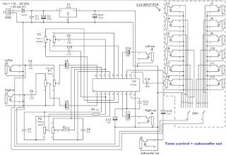
PT2350 is a tone control subwoofer cross-over low pass filter chip utilizing CMOS Technology. It features a tone control range of + 10dB (50Hz, 4 KHz) and subwoofer low pass filter of the second order Sallen Key Design. The roll-off point can be adjusted by changing the value of the external capacitor. Pin assignments and application circuits are optimized for easy PCB Layout and cost saving advantages.
tone control subwoofer


CMOS Technology

2-Channel Input
3-Channel Output (Including 1 stereo Output and Subwoofer Output)
Low Total Harmonic Distortion (THD<0.01%, Subwoofer THD<0.2%)
High S/N Ratio (S/N Ratio <-87dB, A-weighting)
Least External Components
Adjustment of Frequency response by changing the value of the external component
Single Power Supply: 3 to 8.5 Volts
Available in 20 pins, DIP or SO Package

PARTS
Resistors
2------ R1,R2-------------- --------- 10k / 1% / metal film
Capacitors
2------ C9,C10------------- -------- 4.7nF / 63V / polyester / raster R. 5mm
3------ C1,C7,C8-------- ----------- 47nF / 63V / polyester / raster R. 5mm
1------ C16---------------- --------- 100nF / 63V / polyester / raster R. 5mm
1------ C13----------------- -------- 220nF / 63V / polyester / raster R. 5mm
2------ C3,C4------------- --------- 2.2uF / 50V / polyester / raster R. 5mm
5------ C5,C6,C11,C14,C15--- 3.3uF / 100V / electrolytic / vertical / raster R. 5mm
1------ C12-------------------------- 10uF / 35V / 105C / electrolytic / vertical / raster R. 5mm
1------ C17----------------- --------- 100uF / 16V / 105C / electrolytic / vertical / raster R. 5mm
1------ C2---------------------------- 470uF / 35V / electrolytic / vertical / raster R. 5mm
Integrated Circuits
1------ U1---------------------------- 78L08 / +8V voltage regulator / TO-92
1-------U2---------------------------- PT2350 / stereo tone control, subwoofer low pass filter IC / DIP20
Diodes
1------ D1---------------------------- 1N4153
Miscellaneous
1------ J1----------------------------- 2 pole wire connector (terminal block) to pcb / raster r. 5 mm / hight 9.7 mm
1------ P1----------------- ----------- 10k log stereo potentiometer / 6 mm saft
2------ P2,P3------------------------ 100k lin stereo potentiometer / 6 mm saft
5------ J2 to J5---------------------- RCA female to PCB, straight, Hosiden any colour

NOTICE ABOUT J2 to J18 . if you make one stereo input device you need 5 pcs of RCA female as listed in parts list
If you make 2 x 6 input device, you need total quantity of 15 pcs RCA female and also 2 x 6 changeover switch.
Code of J2 to J18 RCA female to PCB, straight, Hosiden, any colour
SW1 2 x 6 changeover High quality DIP rotary switch to PCB 2 x 6, Alcos witch DRS 2-6, 3.2mm saft

Frequency response of tone control unit is flat between 20 Hz … 20 kHz when treble and bass pots are in middle.
Overall gain is approx. 6 dB when treble and bass pots are in middle.
Treble and bass tone control range is approx. 10 dB (50Hz / 4 kHz) with given component values.
Subwoofer cut off frequency can be adjusted by bass potentiometer… with component values as listed above it is as follows : bass pot in minimum (left) -3dB point, 240 Hz / -12dB 450 Hz, bass pot (middle) -3dB point 100 Hz /-12dB 200 Hz, bass pot maximum (right) -3dB point 60 Hz / -12dB 120 Hz.
Distortion was < 0.1 % when input level was < 0.3V rms.
There is no balance adjustment potentiometer in this application, if you need balance, you must add it separately in this device.
[Continue reading...]

30W Audio Amplifier based TDA7296

30W Audio Amplifier based TDA7296
The audio power amplifier of this scheme is a power amplifier based on TDA7296 chip. The audio amplifier is a class AB amplifier, which can be used in high fidelity (stereo, speakers powered car, TV five stars). The maximum output power obtained with TDA7296 amplifier circuit is about 60 watts. Thanks to the wide range of voltages and high power output capability is able to provide the highest power in 4 and 8 ohm impedance load.

The TDA7296 is provided with both stand-by and mute two independently driven by CMOS logic input pin compatible and optimized to avoid any kind of uncontrolled audible transient at the output. The maximum power of 60 watts is obtained with a power supply around 29V VS = ± 8 ohm load impedance, VS = ± 24V, 6-ohm load impedance, VS = ± 22V 4-ohm impedance loading.

The 60-watt maximum power delivery of the audio circuit is obtained with a 10% total harmonic distortion. Use a power supply around VS = ± 24V, 8 ohm load impedance, VS = ± 21V, 6-ohm load impedance, VS = ± 18V 4-ohm load impedance of the maximum power delivered by the amplifier is 30W, but the total harmonic distortion is about 0.5%. Key features of this amplifier are: high output power, high voltage 30V operation, the mute and standby functions, thermal shutdown and short circuit protection.

Soure : electroniq.net
[Continue reading...]

60 Watts mono Amp


This is a circuit diagram of 60 Watts output class B power amplifier. The supply voltage is 48 Volts. We recommend not increasing the voltage if you want to run the amp long time. You can build this amplifier for low cost. The output transistors are 2N 3055 which are not expensive.

Circuit diagram shown a one amplifier means mono amp, if you want stereo amplifier which is 60W + 60W then you have to build two sets of this. Remember this is not for a beginner, you need to have some experience with electronic circuit diagrams and components before you start this project.


[Continue reading...]

Monday, April 8, 2013

USB Soundcard Circuit with PCM2702

Creating a sound card is not more complex problems. If you use Great IC PCM2702 from Burr RED / Texas Instruments you can create a card USB sound fully functional. The sound card can be activated from the USB port and has one stereo output.


You do not need to install drivers for Windows XP and Vista, because the driver is already in the system, XP and Vista. So this series is really plug and play.

USB Soundcard Circuit with PCM2702
Block Diagram
Description
The core of this construction is a 16-Bit Stereo Digital-To-Analog Converter with PCM2702 USB interface.

USB Soundcard Circuit with PCM2702
Schematic diagram USB soundcard


PCM2702 only requires a few additional components to work. This scheme is not complex. The sound card can be activated directly from the USB port (jumper W1) or from an external power supply (jumper W3). PCM2702 requires two 3.3V power supply (3V-3.6V) and 5V (4.5V-5.5V). I use a fixed output voltage to 3.3V LDO TPS76733Q (IO2) and the output voltage is adjusted to 5V LDO TPS76701Q (IO3).


LDO Both are produced by TI, I use it because there in my drawer. Each LDO The same can be used. IO3 output voltage should be set to slightly lower than the input voltage to enable LDO stabilization is good, in my case the output voltage set to 4.8V. output voltage can be set by the resistor R33 is adjusted. In the case of low power supply, IO3 be shorted by the W3 jumper. Signalizes D3 LED power on.

USB Soundcard Circuit with PCM2702
PCB line design usb soundcard

USB Soundcard Circuit with PCM2702
Layout PCB usb soundcard


Small ferrite beads are placed before all power pins on the PCM2702 and GND Vbus and USB. Small beads reduce high frequency hum. I have a problem finding SMD ferrite beads small local shops but finally I get some of them from the old hard drive. They are not really necessary, you can use zero ohm resistors instead of them.


Low-pass filter placed in the output signal path to reduce the sampling frequency. OPA2353UA dual op amp configured as two stereo-order low-pass filter. Led diodes D1 illuminates when the PCM2702 play audio data received from the USB bus. Diode D2 Led illuminates when the USB bus audio delay the transmission of data to the PCM2702.

USB Soundcard Circuit with PCM2702
Installed component USB soundcard

This circuit works very well. I just had shorted crystal during soldering so that circuit does not work, but after removing the short noise, a sound card to work. I have been tested on Windows 2000, XP and Vista. The electronic circuit works in all the systems mentioned. Driver is in the operating system so that the sound card is ready within a few seconds after you connect the electronic circuit is with a PC / Laptop / Notebook you are in trouble with the sound card / sound card that.

During writing this article I have found that the PCM2702 is now not recommended for new designs, but TI offers a better solution. PCM2704, PCM2705 has the same functions as the PCM2702, but they include an output filter. They were able to push the headphones directly.

Volume and mute can be controlled via the SPI bus in PCM2705 or PCM2704 with pushbuttons in the case. PCM2704 and PCM2705 are in TSSOP28 package. PCM2706 PCM2704 and PCM2707 similar to PCM2705 but in addition they have the I2S bus. PCM2706 and PCM2707 are in a TQFP32 package. I recommend using the new chip (PCM2704 / PCM2705) for the new design an Operating System.
[Continue reading...]

9 Volt Power Supply Circuit Diagram Using IC 7809

You can see below 9 Volt Power Supply Circuit Diagram Using IC 7809


Description        
    Circuit showing a 9 volt power supply .
Here we have used a bridge rectifier and 7809 ic for making this circuit.Where the ic regulate the output to 9 v,1 A .
[Continue reading...]
 
Copyright © 2012. Raul's Diagrams Collection - Posts · Comments
Powered by Blogger