Tuesday, July 30, 2013

Digital Dice Circuit diagram

This is digital dice circuit diagram.Here I have used IC CD4060B.After pressing.S2 to to play you will be able to listen a sound too.I think this will be a wonderful circuit for you all.now you can play your games with your digital dice.


Note
# This circuit operates with 9V power supply
# Build this circuit on a PCB.

[Continue reading...]

Monday, July 29, 2013

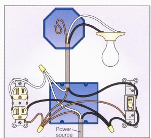
Rewireswitch Controls Outlet Control Overhead Light

Light Switch Wiring on Wiring A Switch  Light First
Wiring A Switch Light First.


Light Switch Wiring on Wiring A Switched Outlet Wiring Diagram   Electrical Online
Wiring A Switched Outlet Wiring Diagram Electrical Online.


Light Switch Wiring on Light With Outlet 2 Way Switch Wiring Diagram
Light With Outlet 2 Way Switch Wiring Diagram.


Light Switch Wiring on Wiring A Light Switch   Electrical Online
Wiring A Light Switch Electrical Online.


Light Switch Wiring on Rewire A Switch That Controls An Outlet To Control An Overhead Light
Rewire A Switch That Controls An Outlet To Control An Overhead Light.


Light Switch Wiring on Switch Light Power Switch
Switch Light Power Switch.


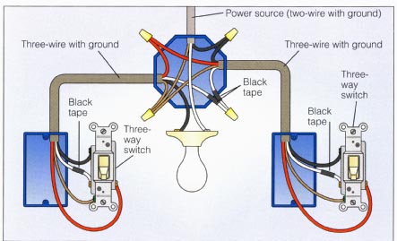
Light Switch Wiring on Way Switch Wiring Diagram Variation  6   Electrical Online
Way Switch Wiring Diagram Variation 6 Electrical Online.


Light Switch Wiring on Way Switch Wiring Diagram Variation  6   Electrical Online
Way Switch Wiring Diagram Variation 6 Electrical Online.


Light Switch Wiring on Two Way Light Switch Using 3 Core Cable
Two Way Light Switch Using 3 Core Cable.


Light Switch Wiring on How To Wire Two Lights On One Switch   Ehow Com
How To Wire Two Lights On One Switch Ehow Com.


[Continue reading...]

Thursday, July 25, 2013

Build a Low voltage regulators Circuit Diagram

These Low voltage regulators Circuit Diagram short-circuit protected regulators give 6, 7, and 9 V from an automobile battery supply of 13 V nominal; however, they will function just as well if connected to a smoothed dc output from a transformer/rectifier circuit. Two types are shown for both positive and negative ground systems. The power transistors can be mounted on the heatsink without a mica insulating spacer thus allowing for greater cooling efficiency. Both circuits are protected against overload or short-circuits. The current cannot exceed 330 mA.

Under normal operating conditions the voltage across R2 does not rise above the 500 mV necessary to turn Q2 on and the circuit behaves as if there was only Q1 present. If excessive current is drawn, Q2 turns on and cuts off Ql, protecting the regulating transistor. The table gives the values of Rl for different zener voltages.

 Low voltage regulators Circuit Diagram

Low voltage regulators Circuit Diagram

[Continue reading...]

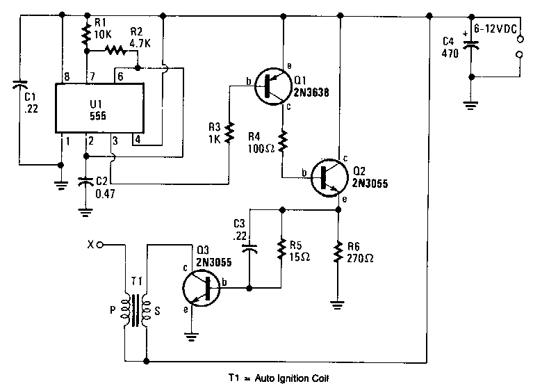
Battery powered high voltage generator Circuit Diagram

Battery-powered-high-voltage-generator Circuit Diagram . Output voltage great enough to jump a l-inch gap can be obtained from a 12-V power source. A 555 timer IC is connected as an astable multivibrator that produces a narrow negative pulse at pin 3. The pulse turns Ql on for the duration of the time period. The collector of Ql is direct-coupled to tbe base of tbe power transistor Q2, turning it on during the same time period.  

The emitter of Q2 is direct -coupled through current limiting resistor R5 to the base of the power transistor. Q3 switches on, producing a minimum resistance between the collector and emitter. The high-current pulse going through tbe primary of high-voltage transformer Tl generates a very high pulse voltage at its secondary output terminal (labeled X). The pulse frequency is determined by tbe values of Rl, R2, and C2. The values given in the parts list were chosen to give the best possible performance when an auto-ignition coil is used for Tl.  

Battery-powered-high-voltage-generator Circuit Diagram

Battery-powered-high-voltage-generator Circuit Diagram
[Continue reading...]
 
Copyright © 2012. Raul's Diagrams Collection - Posts · Comments
Powered by Blogger