Showing posts with label voltage. Show all posts

Monday, September 30, 2013

Low Voltage Remote Mains Switch

This circuit allows a 240V mains appliance to be controlled remotely via low-voltage cabling and a pushbutton switch. The mains appliance (in this case, a light bulb) is switched with a suitably-rated relay. All of the electronics is housed in an ABS box located in proximity to the appliance. The pushbutton switch and plugpack are located remotely and can be wired up with 3-core alarm cable or similar. Cable lengths of 20m or more are feasible with this arrangement. When the switch (S1) is pressed, the input (pin 8) of IC1c is briefly pulled low via the 10mF capacitor, which is initially discharged.

Low-voltage remote mains switch circuit schematic

The output (pin 10) immediately goes high and this is inverted and fed back to the second input (pin 9) via another gate in the quad NAND package (IC1d). In conjunction with the 1MW resistor and 470nF capacitor, IC1d eliminates the effects of contact "bounce" by ensuring that IC1c’s output remains high for a predetermined period. The output from IC1c drives the clock input of a 4013 D-type flip-flop (IC2). The flipflop is wired for a "toggle" function by virtue of the Q-bar connection back to the D input. A 2.2MW resistor and 100nF capacitor improve circuit noise immunity. Each time the switch is pressed, the flipflop output (pin 13) toggles, switching the transistor (Q1) and relay on or off. Note that all mains wiring must be properly installed and completely insulated so that there is no possibility of it contacting the low-voltage side of the circuit.
[Continue reading...]

Thursday, July 25, 2013

Build a Low voltage regulators Circuit Diagram

These Low voltage regulators Circuit Diagram short-circuit protected regulators give 6, 7, and 9 V from an automobile battery supply of 13 V nominal; however, they will function just as well if connected to a smoothed dc output from a transformer/rectifier circuit. Two types are shown for both positive and negative ground systems. The power transistors can be mounted on the heatsink without a mica insulating spacer thus allowing for greater cooling efficiency. Both circuits are protected against overload or short-circuits. The current cannot exceed 330 mA.

Under normal operating conditions the voltage across R2 does not rise above the 500 mV necessary to turn Q2 on and the circuit behaves as if there was only Q1 present. If excessive current is drawn, Q2 turns on and cuts off Ql, protecting the regulating transistor. The table gives the values of Rl for different zener voltages.

 Low voltage regulators Circuit Diagram

Low voltage regulators Circuit Diagram

[Continue reading...]

Battery powered high voltage generator Circuit Diagram

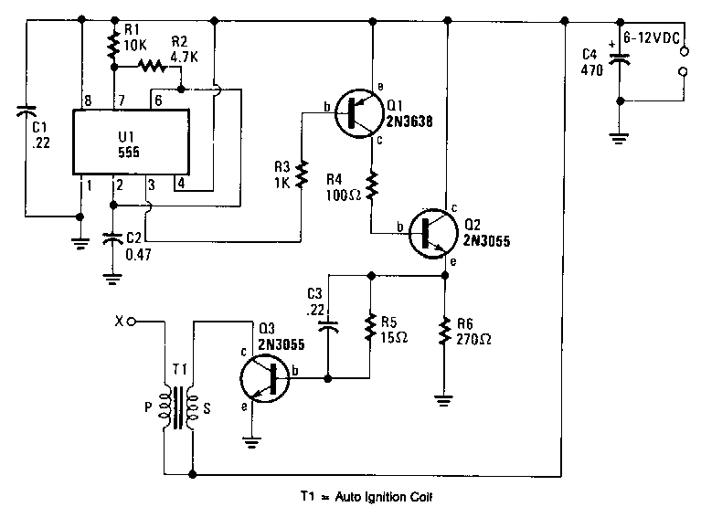
Battery-powered-high-voltage-generator Circuit Diagram . Output voltage great enough to jump a l-inch gap can be obtained from a 12-V power source. A 555 timer IC is connected as an astable multivibrator that produces a narrow negative pulse at pin 3. The pulse turns Ql on for the duration of the time period. The collector of Ql is direct-coupled to tbe base of tbe power transistor Q2, turning it on during the same time period.  

The emitter of Q2 is direct -coupled through current limiting resistor R5 to the base of the power transistor. Q3 switches on, producing a minimum resistance between the collector and emitter. The high-current pulse going through tbe primary of high-voltage transformer Tl generates a very high pulse voltage at its secondary output terminal (labeled X). The pulse frequency is determined by tbe values of Rl, R2, and C2. The values given in the parts list were chosen to give the best possible performance when an auto-ignition coil is used for Tl.  

Battery-powered-high-voltage-generator Circuit Diagram

Battery-powered-high-voltage-generator Circuit Diagram
[Continue reading...]

Saturday, April 13, 2013

Maximum Minimum Voltage Indicator

This\r\n circuit indicates which of three voltages in the vary from about about\r\n -4V to about +4V - at A, B and C - is the very best by way of lights one in all \r\nthree indicator LEDs. Alternatively, it may be wired to point the \r\nlowest of three voltages or to indicate both the easiest and lowest \r\nvoltages. Op amps IC1a, IC1b & IC1c are wired as comparators, while \r\nthe three indicator LEDs and their series 1kO present limiting resistors\r\n are strung across the op amp outputs to put in force the proper logic\r\n operates.

Circuit diagram:
 Maximum Minimum Voltage Indicator Circuit Diagram

For\r\n instance, LED A will gentle only when pin eight of IC1c is low (ie, A larger\r\n B) and pin 7 of IC1b is excessive (ie, A higher C). Similarly, LED B will \r\nlight only when pin 8 of IC1c is high (ie, B larger A) and pin 1 of \r\nIC1a is low (ie, B better C). LED C works in identical fashion if the \r\nvoltage at C is the very best. Note that if the entire LEDs and their \r\nparallel 1N4148 diodes are reversed, the circuit will indicate the \r\nlowest of the three enter voltages. And if each and each 1N4148 diode is replaced\r\n through a LED, the circuit will indicate each the perfect and lowest enters.

Author: Andrew Partridge - Copyright: Silicon Chip
[Continue reading...]

Thursday, April 11, 2013

Mini High Voltage Generator Circuit

Here’s a project that could be useful this summer on the beach, to stop anyone touching your things left on your beach towel while you’ve gone swimming; you might equally well use it at the office or workshop when you go back to work. In a very small space, and powered by simple primary cells or rechargeable batteries, the proposed circuit generates a low-energy, high voltage of the order of around 200 to 400 V, harmless to humans, of course, but still able to give a quite nasty ‘poke’ to anyone who touches it.

Quite apart from this practical aspect, this project will also prove instructional for younger hobbyists, enabling them to discover a circuit that all the ‘oldies’ who’ve worked in radio, and having enjoyed valve technology in particular, are bound to be familiar with. As the circuit diagram shows, the project is extremely simple, as it contains only a single active element, and then it’s only a fairly ordinary transistor. As shown here, it operates as a low-frequency oscillator, making it possible to convert the battery’s DC voltage into an AC voltage that can be stepped up via the transformer.

Using a centre-tapped transformer as here makes it possible to build a ‘Hartley’ oscillator around transistor T1, which as we have indicated above was used a great deal in radio in that distant era when valves reigned supreme and these was no sign of silicon taking over and turning most electronics into ‘solid state’. The ‘Hartley’ is one of a number of L-C oscillator designs that made it to eternal fame and was named after its invertor, Ralph V.L Hartley (1888-1970). For such an oscillator to work and produce a proper sinewave output, the position of the intermediate tap on the winding used had to be carefully chosen to ensure the proper step-down (voltage reduction) ratio.

Here the step-down is obtained inductively. Here, optimum inductive tapping is not possible since we are using a standard, off-the-shelf transformer. However we’re in luck — as its position in the centre of the winding creates too much feedback, it ensures that the oscillator will always start reliably. However, the excess feedback means that it doesn’t generate sinewaves; indeed, far from it. But that’s not important for this sort of application, and the transformer copes very well with it.

The output voltage may be used directly, via the two current-limiting resistors R2 an R3, which must not under any circum-stances be omitted or modified, as they are what make the circuit safe. You will then get around 200 V peak-to-peak, which is already quite unpleasant to touch. But you can also use a voltage doubler, shown at the bottom right of the figure, which will then produce around 300 V, even more unpleasant to touch. Here too of course, the resistors, now know as R4 and R5, must always be present. The circuit only consumes around a few tens of mA, regardless of whether it is ‘warding off’ someone or not! If you have to use it for long periods, we would however recommend powering it from AAA size Ni-MH batteries in groups of ten in a suitable holder, in order not to ruin you buying dry batteries.

Circuit diagram:
mini-high-voltage-generator-circuit

Warning!
If you build the version without the voltage doubler and measure the output voltage with your multimeter, you’ll see a lower value than stated. This is due to the fact that the waveform is a long way from being a sinewave, and multimeters have trouble interpreting its RMS (root-mean-square) value. However, if you have access to an oscilloscope capable of handling a few hundred volts on its input, you’ll be able to see the true values as stated. If you’re still not convinced, all you need do is touch the output terminals...

To use this project to protect the handle of your beach bag or your attachecase, for example, all you need do is fix to this two small metallic areas, quite close together, each connected to one output terminal of the circuit. Arrange them in such a way that unwanted hands are bound to touch both of them together; the result is guaranteed! Just take care to avoid getting caught in your own trap when you take your bag to turn the circuit off!
 
 
Source by : Streampowers
[Continue reading...]

Wednesday, April 10, 2013

Voltage Tester for Model Batteries

With a suitable load, the terminal voltage of a NiCd or lithium-ion battery is proportional to the amount of stored energy. This relationship, which is linear over a wide range, can be used to build a simple battery capacity meter. 

Circuit Image :
 Voltage Tester for Model Batteries Image
Voltage Tester for Model Batteries Circuit Image 

This model battery tester has two functions: it provides a load for the battery, and at the same time it measures the terminal voltage. In addition, both functions can be switched on or off via a model remote-control receiver, to avoid draining the battery when it is not necessary to make a measurement. The load network, which consists of a BC517 Darlington transistor (T2) and load resistor R11 (15 Ω /5 W), is readily evident. When the load is active, the base of T1 lies practically at ground level. Consequently, T1 conducts and allows one of the LEDs to be illuminated. 

Circuit Diagram :
Voltage Tester for Model Batteries-Circuit Diagram
Voltage Tester for Model Batteries Circuit Diagram

The thoroughly familiar voltmeter circuit, which is based on the LM3914 LED driver, determines which LED is lit. The values of R6 and R7 depend on the type and number of cells in the battery. The objective here is not to measure the entire voltage range from 0 V, but rather to display the portion of the range between the fully charged voltage and the fully discharged voltage. Since a total of ten LEDs are used, the display is very precise. For a NiCd battery with four cells, the scale runs from 4.8 V to 5.5 V when R6 = R7 = 2 kΩ. The measurement scale for a lithium-ion battery with two cells ranges from 7.2 V to 8.0 V if R6 = 2 kΩ and R7 = 1 kΩ. 

For remote-control operation, both jumpers should be placed in the upper position (between pin 1 and the middle pin). In this configuration, either a positive or negative signal edge will start the measurement process. A positive edge triggers IC1a, whose output goes High and triggers IC1b. A negative edge has no effect on IC1a, but it triggers IC1b directly. In any case, the load will be activated for the duration of the pulse from monostable IC1b. Use P12 to set the pulse width of IC1a to an adequate value, taking care that it is shorter than the pulse width of IC1b. 

If the voltage tester is fitted into a remote-controlled model, you can replace the jumpers with simple wire bridges. However, if you want to use it for other purposes, such as measuring the amount of charge left in a video camera battery, it is recommended to connect double-throw push-button switches in place of JP1 and JP2. The normally closed contact corresponds to the upper jumper position,while the normally open contact corresponds to the lower position.

Parts :
Resistors:
R1,R2 = 47kΩ
R3 = 100kΩ
R4 = 500kΩ
R5 = 1kΩ
R6,R7 = see text (1% resistors!)
R8 = 1kΩ5
R9 = 1kΩ2
R10 = 330Ω
R11 = 15Ω 5W
R12 = 15kΩ
P1 = 100kΩ preset
Capacitors:
C1 = 10nF
C2 = 100nF
Semiconductors:
D1-D10 = LED, red, high effi-ciency
T1 = BC557
T2 = BC517
IC1 = 74HC123
IC2 = LM3914AN
Miscellaneous:
PC1,PC2,PC3 = solder pin
JP1,JP2 = jumper or pushbutton

PCB Layout :
B. PCB Laout
Voltage Tester for Model Batteries PCB Layout
 
 
Streampowers
[Continue reading...]

Friday, April 5, 2013

Frequency to Voltage Converter Circuit

IC LM2917 Frequency to Voltage Converter
IC LM2917 IC chip is designed specifically as a Frequency to Voltage Converter or Frequency to Voltage converter. In its use to applications Frequency to Voltage Converter IC LM2917 requires few external components. 
There are several examples of applications of Frequency to Voltage Converter IC LM2917 datasheet that is included in the LM2917 IC. In this article series Frequency to Voltage Converter IC also taken from the LM2917 datasheet. The advantages of single chip LM2917 Frequency to Voltage Converter is able to provide instantaneous volt output o at time of frequency change 0 Hz. Very easy to apply in measuring the output frequency with the formulation of single-chip Frequency to Voltage Converter VOUT = FIN x VCC x R1 x C1.

Then the single-chip LM2917 Frequency to Voltage Converter This configuration requires only the RC only in frequency doubling. And has an internal zener regulator to aimlessly accuracy and stability in frequency-to-voltage conversion process.

Application circuit Figure IC LM2917 as Frequency to Voltage Converter

Feature-owned single-chip LM2917 Frequency to Voltage Converter
Reference to ground directly with variable reluctance
Op Amp / Comparator with transistor output
50 mA maximum output currents for application directly to the load
Frequency doubling for low ripel
Buid in zener
Linear output ± 0.3%
Application single chip LM2917 Frequency to Voltage Converter
Frequency to Voltage Converter
Rotation speed sensor applications
Speedometer
Tachometer
Cruise Control
Cluth Control
And other applications associated with the measurement of rotation speed or frequency measurements.
[Continue reading...]
 
Copyright © 2012. Raul's Diagrams Collection - Posts · Comments
Powered by Blogger