Showing posts with label build. Show all posts

Tuesday, December 17, 2013

Build a Portable GSM900 Cellular Phone Jammer Circuit Diagram

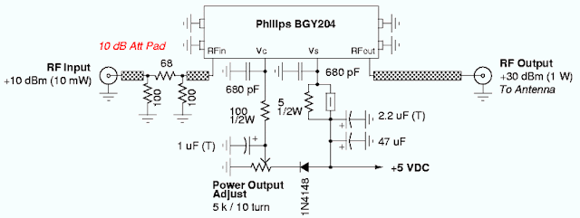
Portable GSM900 Cellular Phone Jammer Circuit Diagram Emits a carrier that sweeps the 925-960 MHz cellular tower transmitter band (handset receive band)

 GSM900 Cellular Phone Jammer Circuit Diagram


GSM900 Cellular Phone Jammer Circuit DiagramGSM900 Cellular Phone Jammer Circuit Diagram
[Continue reading...]

Thursday, July 25, 2013

Build a Low voltage regulators Circuit Diagram

These Low voltage regulators Circuit Diagram short-circuit protected regulators give 6, 7, and 9 V from an automobile battery supply of 13 V nominal; however, they will function just as well if connected to a smoothed dc output from a transformer/rectifier circuit. Two types are shown for both positive and negative ground systems. The power transistors can be mounted on the heatsink without a mica insulating spacer thus allowing for greater cooling efficiency. Both circuits are protected against overload or short-circuits. The current cannot exceed 330 mA.

Under normal operating conditions the voltage across R2 does not rise above the 500 mV necessary to turn Q2 on and the circuit behaves as if there was only Q1 present. If excessive current is drawn, Q2 turns on and cuts off Ql, protecting the regulating transistor. The table gives the values of Rl for different zener voltages.

 Low voltage regulators Circuit Diagram

Low voltage regulators Circuit Diagram

[Continue reading...]

Friday, April 12, 2013

Build LED Light Pen Schematic

Physicians and repair engineers often use small light pens for visual examination purposes. Rugged and expensive as these pens may be, their weak point is the bulb, which is a ‘serviceable’ part. In practice, that nearly always equates to ‘expensive’ and / or ‘impossible to find’ when you need one.

LEDs have a much longer life than bulbs and the latest ultra bright white ones also offer higher energy-to-light conversion efficiency. On the down side, LEDs require a small electronic helper circuit called ‘constant-current source’ to get the most out of them.
 
LED Light Pen Circuit Diagram
LED-Light-Pen-Circuit-Diagram

Here, T1 and R1 switch on the LED. R2 acts as a current sensor with T2 shunting off (most of) T1’s base bias current when the voltage developed across R2 exceeds about 0.65 V. The constant current through the white LED is calculated from

R2 = 0.65 / ILED
With some skill the complete circuit can be built such that its size is equal to an AA battery. The four button cells take the place of the other AA battery that used to be inside the light pen. Link


Author: Myo Min – Copyright: Elektor
[Continue reading...]

Wednesday, April 10, 2013

Let’s to build a mini organ keyboard circuit using UM3511

The previous
day my son said ” A friend has a mini organ. Casio SA-76 44 Key Mini
Keyboard, Orange It is Good quality but expensive.
My son would have
the same. But I said, as we are the Electronic inventor, to try to
create their own. We are proud and cheaper too.
You might like this
mini organ keyboard circuit certainly. Because in addition to the
simple, the price is not expensive, effective really worthwhile.
You may consider the main features of the circuit, as follows.
1. Can works with DC voltage in rang 3-12 Volt by low current consumption.
2. There are the music playback up to 15 keys, or a note from G3-G5.
3. Can be programmed to play. Repeat for up to 47 notes.
4. Can act as a music source by up to 15 songs.(Simple carbohydrates. Press any key. To select the desired song.)
How circuit works
In the heart of the circuit is the UM3511
-IC is designed to act this purpose

-Internal IC consists of a lot. We do not need to explain the
operation of the circuit Internal this IC. Our job only assembly
equipment used in the first the circuit to be completed.
let-s-to-build-a-mini-organ-keyboard-circuit-using-um3511

-From circuit in figure 1 will see that we can connect a output of
pin 5 on the UM3511-IC to drive a transistor output to emit loud sound
out to the speakers directly.
-For the variable resistor-VR1 act as
determine a frequency of the oscillator circuit. When we created
successfully. Should be adjusted to the correct value. When adjusted,
you may use the normal resistor instead.
-The switch-S1 as an
option act the work of circuit that music will be played by the
application of the factory, or will play music as we have played own.
From pushing keyboard as by various notes.
For a list of songs that can be programmed from the factory. Which will play out as We have push switch as follows.
G3 Hush little baby
A3 Twinkle Little Star
C4 Dream of Home and Mother
D4 Christmas Carol
E4 Are You Sleeping
F4 The Famer in the Dell
G4 In a Persian Market
A4 Mary Had a Little Lamp
B4 Long Long Ago
C5 Santa Lucia
D5 Little Brown Jug
E5 Butterfly
F5 The Train is Running Fast
G5 Close Encounters of the Third Kind
How to build and setting
Suppose that you want to play Santa Lucia, it may be done as follows.
1. Hit the switch S1 to the program.
2. Press the C5 keyboard switch.
Only this time, it will play the music you want to finish it, it will stop automatically.

For convenience we have on the power supply is designed for the 5 volt
dc regulator circuit. To be applied to the input voltage from 6 volt to
24 volt. It also allows the voltage to be smooth, no hum at play.
pcb-of-a-mini-organ-keyboard-circuit
Figure 2 the pcb layout of a mini organ keyboard circuit using UM3511
All components except the transformer and speaker. We can assemble onto the PCB. As shown in Figure 2.

For keyboard switch because we want you to get a feel for the playing.
As the organ of the fact that selling in the shop. We chose to use a
computer key switches.
[Continue reading...]
 
Copyright © 2012. Raul's Diagrams Collection - Posts · Comments
Powered by Blogger