Showing posts with label with. Show all posts

Saturday, September 28, 2013

Alarm Clock With Day Selector

This circuit disables an alarm clock on Saturdays and Sundays when people like to sleep in but enables normal operation on Mondays to Fridays so that people rise in time for work or school. The core of the circuit is a 4017 decade counter which acts as the day counter and it is used in conjunction with a desk clock which acts the alarm and a watch module with alarm function which provides one clock pulse very day to the 4017. In operation, the watch module feeds a day pulse via transistor Q3 to the clock input of IC1. This has seven outputs connected via day switches (S1-S7) and diodes D3-D9 to Q1 which disables the alarm signal to the speaker via transistor Q2. LEDs1-7 indicate the actual day (if you forget!).

To set the system, set the desk clock for the correct time and for the desired alarm time (eg, 6’o’clock). The watch module is set to the correct time and its alarm set to midnight. The day counter, IC1, is set to the correct day, as indicated by the LEDs, by pushing switch S12 and closing switch S8 or S9. S8 is normally left open to conserve the battery by leaving the LEDs off. As shown on the circuit, switches S1-S7 are set to sound the alarm on Mondays to Fridays and disable it on Saturday and Sunday. However, you can change the days to suit your work habits.
[Continue reading...]

Sunday, April 21, 2013

LED FLASHER WITH ONE TRANSISTOR


This is a unique flasher circuit employing a single driver transistor that takes its flash-rate from a flashing LED. The flasher within the photo is 3mm. An ordinary LED wont work. The flash rate can not be altered by the brightness of the high-bright white LED will be adjusted by altering the 1k resistor across the 100u electrolytic to 4k7 or 10k. The 1k resistor discharges the 100u in order that when the transistor activates, the charging current into the 100u illuminates the white

LED.
If a 10k discharge resistor is used, the 100u isnt absolutely discharged and therefore the LED doesnt flash as bright. All the components within the photo are within the same places as within the circuit diagram to make it simple to envision how the components are connected.

The circuit uses a flashing LED to flash a super-bright 20,000mcd white LED

[Continue reading...]

Wednesday, April 10, 2013

With Auto Sound Systems Newest Technology isnt Necessarily Greatest Technology

We live in a world where music is our constant companion. We take it with us to the beach, to work, to exercise, even while riding bikes or talking on our cell phones. It only makes sense that in our cars we would like to have the best possible auto sound systems our hard earned dollars can buy. The problem is that new technology is being introduced to the market each and every day and many of us feel as though if we hold our breath just a little bit longer something even better and more spectacular will come along. We know that we will absolutely want to kick ourselves if we buy in to "this or that" companys auto sound system that was phenomenal yesterday, just before the next great thing hits the market.


The truth is that superior auto sound system technology exists already and the question isnt if it will hit the market but rather when. And when seems to be a pretty big question when it comes to emerging technologies. There are always so many things that control when the actual product will hit the shelves in stores or even how much supply will be available at that point in time. The really good news for consumers is that if you wait until that point, chances are the prices on the system you like now will probably lower significantly almost overnight.

While the geek in me would love to have the latest and greatest of gadgets at all times, the mom in me knows that the kids will need braces, new shoes for soccer, and (eventually) college tuition. For those reasons, I will continue typing on my sadly outdated eMachine and secretly long for the brand new Dell notebook while listening to the latest tunes on my iPod Shuffle while secretly longing for one of the new iPods, which is capable of playing video. I will live however, and will enjoy watching others play with their new gadget goodies while I learn about them and wait for the prices to drop (just like DVD players a few years back).

I am at least intelligent enough to realize that most of the time it is best not to be the first to buy a new product or an emerging technology. Let someone else take the risks associated with buying an essentially untried product while I sit back and listen to what they have to say. This way I can make an informed decision without bearing the scars associated with testing an untried product.

There are many things Im willing to sacrifice and many more things I give to my children as guinea pigs. The thing I have noticed quite often with them is that if it can survive a few weeks in their care, it is a pretty safe bet and might even be worth purchasing stock in the company. We all have some things that are more important to us than others and while I love technology there are other things I love more.

Music, however, is a very important part of my life and I do try to keep current with the latest and greatest when it comes to auto sound systems. My favorite at the moment is the Bose. Every piece of this equipment is designed with the idea of making music sound, as it should. You can get the biggest and greatest sound quality from this system without giving up half your trunk or your entire back seat. Bose is one of the more expensive products on the market when it comes to auto sound systems but it is well worth every penny.

When checking out your options for an auto sound system be sure to keep in mind that the most expensive product is not necessarily the best product-no matter what the salesman tells you. By learning as much as possible about all choices you may find that one of the less expensive systems is actually better suited for your auto sound system needs.

[Continue reading...]

Monday, April 8, 2013

USB Soundcard Circuit with PCM2702

Creating a sound card is not more complex problems. If you use Great IC PCM2702 from Burr RED / Texas Instruments you can create a card USB sound fully functional. The sound card can be activated from the USB port and has one stereo output.


You do not need to install drivers for Windows XP and Vista, because the driver is already in the system, XP and Vista. So this series is really plug and play.

USB Soundcard Circuit with PCM2702
Block Diagram
Description
The core of this construction is a 16-Bit Stereo Digital-To-Analog Converter with PCM2702 USB interface.

USB Soundcard Circuit with PCM2702
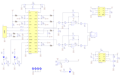
Schematic diagram USB soundcard


PCM2702 only requires a few additional components to work. This scheme is not complex. The sound card can be activated directly from the USB port (jumper W1) or from an external power supply (jumper W3). PCM2702 requires two 3.3V power supply (3V-3.6V) and 5V (4.5V-5.5V). I use a fixed output voltage to 3.3V LDO TPS76733Q (IO2) and the output voltage is adjusted to 5V LDO TPS76701Q (IO3).


LDO Both are produced by TI, I use it because there in my drawer. Each LDO The same can be used. IO3 output voltage should be set to slightly lower than the input voltage to enable LDO stabilization is good, in my case the output voltage set to 4.8V. output voltage can be set by the resistor R33 is adjusted. In the case of low power supply, IO3 be shorted by the W3 jumper. Signalizes D3 LED power on.

USB Soundcard Circuit with PCM2702
PCB line design usb soundcard

USB Soundcard Circuit with PCM2702
Layout PCB usb soundcard


Small ferrite beads are placed before all power pins on the PCM2702 and GND Vbus and USB. Small beads reduce high frequency hum. I have a problem finding SMD ferrite beads small local shops but finally I get some of them from the old hard drive. They are not really necessary, you can use zero ohm resistors instead of them.


Low-pass filter placed in the output signal path to reduce the sampling frequency. OPA2353UA dual op amp configured as two stereo-order low-pass filter. Led diodes D1 illuminates when the PCM2702 play audio data received from the USB bus. Diode D2 Led illuminates when the USB bus audio delay the transmission of data to the PCM2702.

USB Soundcard Circuit with PCM2702
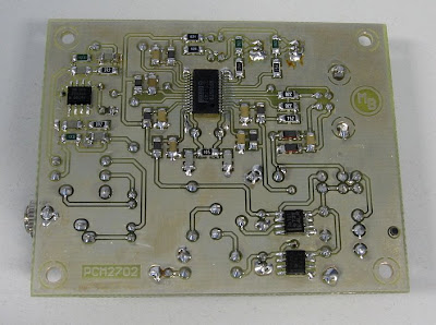
Installed component USB soundcard

This circuit works very well. I just had shorted crystal during soldering so that circuit does not work, but after removing the short noise, a sound card to work. I have been tested on Windows 2000, XP and Vista. The electronic circuit works in all the systems mentioned. Driver is in the operating system so that the sound card is ready within a few seconds after you connect the electronic circuit is with a PC / Laptop / Notebook you are in trouble with the sound card / sound card that.

During writing this article I have found that the PCM2702 is now not recommended for new designs, but TI offers a better solution. PCM2704, PCM2705 has the same functions as the PCM2702, but they include an output filter. They were able to push the headphones directly.

Volume and mute can be controlled via the SPI bus in PCM2705 or PCM2704 with pushbuttons in the case. PCM2704 and PCM2705 are in TSSOP28 package. PCM2706 PCM2704 and PCM2707 similar to PCM2705 but in addition they have the I2S bus. PCM2706 and PCM2707 are in a TQFP32 package. I recommend using the new chip (PCM2704 / PCM2705) for the new design an Operating System.
[Continue reading...]

Saturday, April 6, 2013

Automatic Night Lamp with Morning Alarm

This circuit automatically turns on a night lamp when bedroom light is switched off. The lamp remains ‘on’ until the light sensor senses daylight in the morning. A super-bright white LED is used as the night lamp. It gives bright and cool light in the room. When the sensor detects the daylight in the morning, a melodious morning alarm sounds. The circuit is powered from a standard 0-9V transformer. Diodes D1 through D4 rectify the AC voltage and the resulting DC voltage is smoothed by C1. Regulator IC 7806 gives regulated 6V DC to the circuit. A battery backup is provided to power the circuit when mains fails. When mains supply is available, the 9V rechargeable battery charges via diode D5 and resistor R1 with a reasonably constant current. In the event of mains failure, the battery automatically takes up the load without any delay. Diode D5 prevents the battery from discharging backwards following the mains failure and diode D6 provides current path from the battery.

Automatic Night Lamp with Morning Alarm Circuit Diagram

Automatic Night Lamp with Morning Alarm-Circuit-Diagram

The circuit utilises light-dependant resistors (LDRs) for sensing darkness and light in the room. The resistance of LDR is very high in darkness, which reduces to minimum when LDR is fully illuminated. LDR1 detects darkness, while LDR2 detects light in the morning. The circuit is designed around the popular timer IC NE555 (IC2), which is configured as a monostable. IC2 is activated by a low pulse applied to its trigger pin 2. Once triggered, output pin 3 of IC2 goes high and remains in that position until IC2 is triggered again at its pin 2. When LDR1 is illuminated with ambient light in the room, its resistance remains low, which keeps trigger pin 2 of IC2 at a positive potential. As a result, output pin 3 of IC2 goes low and the white LED remains off. As the illumination of LDR1’s sensitive window reduces, the resistance of the device increases.

In total darkness, the specified LDR has a resistance in excess of 280 kilo-ohms. When the resistance of LDR1 increases, a short pulse is applied to trigger pin 2 of IC2 via resistor R2 (150 kilo-ohms). This activates the monostable and its output goes high, causing the white LED to glow. Low-value capacitor C2 maintains the monostable for continuous operation, eliminating the timer effect. By increasing the value of C2, the ‘on’ time of the white LED can be adjusted to a predetermined time. LDR2 and associated components generate the morning alarm at dawn. LDR2 detects the ambient light in the room at sunrise and its resistance gradually falls and transistor T1 starts conducting. When T1 conducts, melody-generator IC UM66 (IC3) gets supply voltage from the emitter of T1 and it starts producing the melody. The musical tone generated by IC3 is standard 0-9V transformer. Diodes D1 through D4 rectify the AC voltage and the resulting DC voltage is smoothed by C1. Regulator IC 7806 gives regulated 6V DC to the circuit.
A battery backup is provided to power the circuit when mains fails. When mains supply is available, the 9V rechargeable battery charges via diode D5 and resistor R1 with a reasonably constant current. In the event of mains failure, the battery automatically takes up the load without any delay. Diode D5 prevents the battery from discharging backwards following the mains failure and diode D6 provides current path from the battery.
The circuit utilises light-dependant resistors (LDRs) for sensing darkness and light in the room. The resistance of LDR is very high in darkness, which reduces to minimum when LDR is fully illuminated. LDR1 detects darkness, while LDR2 detects light in the morning. The circuit is designed around the popular timer IC NE555 (IC2), which is configured as a monostable. IC2 is activated by a low pulse applied to its trigger pin 2. Once triggered, output pin 3 of IC2 goeshigh and remains in that position until IC2 is triggered again at its pin 2. When LDR1 is illuminated with ambient light in the room, its resistance remains low, which keeps trigger pin 2 of IC2 at a positive potential. As a result, output pin 3 of IC2 goes low and the white LED remains off. As the illumination of LDR1’s sensitive window reduces, the resistance of the device increases.

In total darkness, the specified LDR has a resistance in excess of 280 kilo-ohms. When the resistance of LDR1 increases, a short pulse is applied to trigger pin 2 of IC2 via resistor R2 (150 kilo-ohms). This activates the monostable and its output goes high, causing the white LED to glow. Low-value capacitor C2 maintains the monostable for continuous operation, eliminating the timer effect. By increasing the value of C2, the ‘on’ time of the white LED can be adjusted to a predetermined time. LDR2 and associated components generate the morning alarm at dawn. LDR2 detects the ambient light in the room at sunrise and its resistance gradually falls and transistor T1 starts conducting. When T1 conducts, melody-generator IC UM66 (IC3) gets supply voltage from the emitter of T1 and it starts producing the melody. The musical tone generated by IC3 is amplified by single-transistor amplifier T2. Resistor R7 limits the current to IC3 is amplified by single-transistor amplifier T2. Resistor R7 limits the current to IC3 and zener diode ZD limits the voltage to a safer level of 3.3 volts.

The circuit can be easily assembled on a general-purpose PCB. Enclose it in a good-quality plastic case with provisions for LDR and LED. Use a reflective holder for white LED to get a spotlight effect for reading. Place LDRs away from the white LED, preferably on the backside of the case, to avoid unnecessary illumination. The speaker should be small so as to make the gadget compact.

Source:   http://www.ecircuitslab.com/2012/02/automatic-night-lamp-with-morning-alarm.html
[Continue reading...]

Friday, April 5, 2013

1000W ICs audio amplifier with PA03

This is a series of amplifiers are based on the most high-ic power that I have ever known. Because the output is issued up to 1000 watts with the impedance RL 4Ohm. Current supply 120mA, and 30A output current. Minimum input voltage of about 30V and a maximum voltage up to 150V. This is an audio amplifier that I have come across use ICs that maximum voltage up to 150V and output power up to 1000W , the scheme below gan.
1000W ICs audio power amplifier


Part List
Resistor
R1 = 10K
R2 = 10K
R3 = 220K
R4 = 0.18R 5W
R5 = 2.2R 2W
R6 = 0.18R 5W
Capacitor
C1 = 1uF
C2 = 1000uF
C3 = 68pF
C4 = 1000uF
Inductor
L1 = 4MH
IC
U1 = PA03

[Continue reading...]

Wednesday, April 3, 2013

Short Circuit Protection With A MOSFET

If you have an application in which a MOSFET is already used to switch a load, it is relatively easy to add short-circuit or overload protection. Here we make use of the internal resistance RDS(ON), which produces a voltage drop that depends on the amount of current flowing through the MOSFET. The voltage across the internal resistance can be sensed using simple comparator or even a transistor, which switches on at a voltage of around 0.5V. You can thus avoid the use of a sense resistor (shunt), which usually produces an undesirable extra voltage drop. The comparator can be monitored by a microcontroller. In case of an overload, the software can initiate suitable countermeasures (PWM regulation, alarm, emergency stop etc.). It is also conceivable to connect the comparator output directly to the gate of the MOSFET, in order to immediately cut off the transistor in case of a short circuit.

Short-Circuit Protection With A MOSFET Circuit Diagram
[Continue reading...]
 
Copyright © 2012. Raul's Diagrams Collection - Posts · Comments
Powered by Blogger