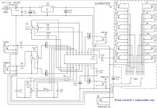
PT2350 is a tone control subwoofer cross-over low pass filter chip utilizing CMOS Technology. It features a tone control range of + 10dB (50Hz, 4 KHz) and subwoofer low pass filter of the second order Sallen Key Design. The roll-off point can be adjusted by changing the value of the external capacitor. Pin assignments and application circuits are optimized for easy PCB Layout and cost saving advantages.
CMOS Technology
2-Channel Input
3-Channel Output (Including 1 stereo Output and Subwoofer Output)
Low Total Harmonic Distortion (THD<0.01%, Subwoofer THD<0.2%)
High S/N Ratio (S/N Ratio <-87dB, A-weighting)
Least External Components
Adjustment of Frequency response by changing the value of the external component
Single Power Supply: 3 to 8.5 Volts
Available in 20 pins, DIP or SO Package
PARTS
Resistors
2------ R1,R2-------------- --------- 10k / 1% / metal film
Capacitors
2------ C9,C10------------- -------- 4.7nF / 63V / polyester / raster R. 5mm
3------ C1,C7,C8-------- ----------- 47nF / 63V / polyester / raster R. 5mm
1------ C16---------------- --------- 100nF / 63V / polyester / raster R. 5mm
1------ C13----------------- -------- 220nF / 63V / polyester / raster R. 5mm
2------ C3,C4------------- --------- 2.2uF / 50V / polyester / raster R. 5mm
5------ C5,C6,C11,C14,C15--- 3.3uF / 100V / electrolytic / vertical / raster R. 5mm
1------ C12-------------------------- 10uF / 35V / 105C / electrolytic / vertical / raster R. 5mm
1------ C17----------------- --------- 100uF / 16V / 105C / electrolytic / vertical / raster R. 5mm
1------ C2---------------------------- 470uF / 35V / electrolytic / vertical / raster R. 5mm
Integrated Circuits
1------ U1---------------------------- 78L08 / +8V voltage regulator / TO-92
1-------U2---------------------------- PT2350 / stereo tone control, subwoofer low pass filter IC / DIP20
Diodes
1------ D1---------------------------- 1N4153
Miscellaneous
1------ J1----------------------------- 2 pole wire connector (terminal block) to pcb / raster r. 5 mm / hight 9.7 mm
1------ P1----------------- ----------- 10k log stereo potentiometer / 6 mm saft
2------ P2,P3------------------------ 100k lin stereo potentiometer / 6 mm saft
5------ J2 to J5---------------------- RCA female to PCB, straight, Hosiden any colour
NOTICE ABOUT J2 to J18 . if you make one stereo input device you need 5 pcs of RCA female as listed in parts list
If you make 2 x 6 input device, you need total quantity of 15 pcs RCA female and also 2 x 6 changeover switch.
Code of J2 to J18 RCA female to PCB, straight, Hosiden, any colour
SW1 2 x 6 changeover High quality DIP rotary switch to PCB 2 x 6, Alcos witch DRS 2-6, 3.2mm saft
Frequency response of tone control unit is flat between 20 Hz … 20 kHz when treble and bass pots are in middle.
Overall gain is approx. 6 dB when treble and bass pots are in middle.
Treble and bass tone control range is approx. 10 dB (50Hz / 4 kHz) with given component values.
Subwoofer cut off frequency can be adjusted by bass potentiometer… with component values as listed above it is as follows : bass pot in minimum (left) -3dB point, 240 Hz / -12dB 450 Hz, bass pot (middle) -3dB point 100 Hz /-12dB 200 Hz, bass pot maximum (right) -3dB point 60 Hz / -12dB 120 Hz.
Distortion was < 0.1 % when input level was < 0.3V rms.
There is no balance adjustment potentiometer in this application, if you need balance, you must add it separately in this device.