Saturday, August 31, 2013

LED Chaser Circuit

Description
I dont know why, but people like blinking lights. You see LED chasers everywhere, in TV shows (Knight Rider), movies, and store windows. This schematic is my version of a simple 10 LED chaser. There is no 555 timer used because at my local electronics store they are over $4 Cdn. Instead, an oscillator made up of two sections of a 4011 NAND gate is employed. This chip is very inexpensive and extremely common.
Circuit Diagram
Parts:
R1 1 Meg 1/4W Resistor
R2 100K Pot
R3 1K 1/4W Resistor or 220Ohm if using blue LEDs
C1 0.1uF 16V Ceramic Disk Capacitor
U1 4011 CMOS NAND Gate
U2 4017 CMOS Counter
LED1-10 LEDs Of Any Colour
MISC Board, Sockets For ICs, Knob For R2
Notes:
1. Use R2 to adjust the "chase rate".
2. You may need to use a lower value resistor if you wish to use blue LEDs. Try 220 Ohm.
3. You can also use incandescent lamps instead of LEDs. Use transistors to drive them by connecting the base of the transistors to each of the outputs of the 4017 through a 1K resistor. Connect one end of the lamp to the positive supply. Then connect the other end to the collector of the transistor. The emitter then goes to ground. Depending on the lamps, you may need power transistors that are heat sinked.
4. C1 may be replaced with a larger value for a slower "chase rate".
5. If you have problems with weird circuit behavior, try replacing R1 with a 33K resistor, and increasing C1 to 1uF.
6. If you plan to use this circuit in your car, be warned that in some areas it is illegal to have red, blue or yellow flashing lights unless you are an emergency vehicle.

[Continue reading...]

Thursday, August 15, 2013

Buy Schumacher XC103 SpeedCharge Battery Charger with Engine Start

Schumacher XC103 SpeedCharge Battery Charger with Engine StartI really wanted to like this charger: Schumacher XC103 SpeedCharge Battery Charger with Engine Start. On paper it seems to do everything I need. The big problem is that it keeps generating an F06 error code when charging on the Fast Charge Rate setting. The manual says this means "The charger detected that the battery may be getting too hot (thermal runaway)." and that "The charger automatically shuts the current off if it detects the battery may be getting too hot or the battery may have a shorted cell. Have the battery checked or replaced." This means the charging is stopped before the battery is fully charged.
The charger generates the F06 code on two different brand new batteries. Also, if I use the Slow Charge Rate setting the same batteries charge just fine so I do not believe that the batteries are defective. There must be something wrong in the charging logic for the Fast Charge Rate setting.

I tried several times to get Schumacher customer support to help me resolve the problem. The Schumacher support staff is useless. They kept sending me the section from the manual that describes the F06 error code. I already knew this information; which I carefully explained on my initial e-mail to Schumacher and on all subsequent e-mails to Schumacher. They persisted in not answering any of my questions, but just resent the F06 error code section from the manual. When I finally insisted that the charger must be defective Schumacher finally agreed to replace the charger with a new or refurbished charger. Since I just bought the charger a refurbished charger was not an option in my opinion.

Moreinfo price here Buy Schumacher XC103 SpeedCharge Battery Charger with Engine Start
[Continue reading...]

Tuesday, August 13, 2013

Vehicle Wiring Products Powerconn

Vehicle Wiring Products on For Car Wiring Harness  For Car Wiring Harness Brand Name  Type  Model
For Car Wiring Harness For Car Wiring Harness Brand Name Type Model.


Vehicle Wiring Products on Car Amplifier Wiring Kit With Different Kinds Of Power Cable   Speaker
Car Amplifier Wiring Kit With Different Kinds Of Power Cable Speaker.


Vehicle Wiring Products on 304  330  334  336  342  344  346  452  367  368  391  392
304 330 334 336 342 344 346 452 367 368 391 392.


Vehicle Wiring Products on Tough Plastic Construction With Hinged Lid To
Tough Plastic Construction With Hinged Lid To.


Vehicle Wiring Products on Engine Wiring Diagram 1  How To Wire A Car Engine   Prestolite Wire
Engine Wiring Diagram 1 How To Wire A Car Engine Prestolite Wire.


Vehicle Wiring Products on Http   Www Vehicle Wiring Products E   Hoto R100r Jpg
Http Www Vehicle Wiring Products E Hoto R100r Jpg.


Vehicle Wiring Products on Performance Products 10123   Painless Muscle Car Wiring Harnesses
Performance Products 10123 Painless Muscle Car Wiring Harnesses.


Vehicle Wiring Products on Automotive Wire Harness Products From China  Mainland  Buy Automotive
Automotive Wire Harness Products From China Mainland Buy Automotive.


Vehicle Wiring Products on Http   Www Vehicle Wiring Products E    Php Powerconn
Http Www Vehicle Wiring Products E Php Powerconn.


Vehicle Wiring Products on Http   Www Vehicle Wiring Products Eu Vwp    Photo Lfb06 Jpg
Http Www Vehicle Wiring Products Eu Vwp Photo Lfb06 Jpg.


[Continue reading...]

Sunday, August 11, 2013

2007 Toyota FJ Cruiser Stop Light Switch Wiring Diagram

,This is a duplex system that transmits two signals: STP and ST1-.The ECM Uses these signals to monitor the brake, whether or not the brake system is working properly. There ‘s only one signal to be detected at one time, this is either signal which is indicate the brake pedal is being depressed or the signal which is indicate that the brake pedal is being released. If the both signals are detected simultaneously, the ECM intrepets this as a malfunction in the light switch and sets the DTC. The Wiring Diagram below shows the Toyota FJ Cruiser Stop Light Switch Wiring Diagram.


[Continue reading...]

Friday, August 9, 2013

Basic Electrical Wiringbasic Electrical Wiring Project Beginner

Electrical Wiring Diagrams on Electrical Wiring Diagram Workbook Body Electrical Practice Electrical
Electrical Wiring Diagram Workbook Body Electrical Practice Electrical.


Electrical Wiring Diagrams on Automotive   Toyota Tags  Electrical System   Wiring Diagram
Automotive Toyota Tags Electrical System Wiring Diagram.


Electrical Wiring Diagrams on 1964 Gmc Truck Electrical System Wiring Diagram   Circuit Schematic
1964 Gmc Truck Electrical System Wiring Diagram Circuit Schematic.


Electrical Wiring Diagrams on Basic Electrical Wiring   Basic Electrical Wiring Project Beginner
Basic Electrical Wiring Basic Electrical Wiring Project Beginner.


Electrical Wiring Diagrams on Lexus Es300 Wiring Diagram Manual Wiring Schematic
Lexus Es300 Wiring Diagram Manual Wiring Schematic.


Electrical Wiring Diagrams on Speaking Of 3 Wire Cable  Romex 12 3 Has A Black Wire For Hot  A Red
Speaking Of 3 Wire Cable Romex 12 3 Has A Black Wire For Hot A Red.


Electrical Wiring Diagrams on 1997 Honda Civic Electrical Wiring Diagram   Circuit Schematic
1997 Honda Civic Electrical Wiring Diagram Circuit Schematic.


Electrical Wiring Diagrams on Electrical Wiring Homes   Howishow Answers Search Engine
Electrical Wiring Homes Howishow Answers Search Engine.


Electrical Wiring Diagrams on Daihatsu Charade Electrical Wiring Diagram     Circuit Diagram Wiring
Daihatsu Charade Electrical Wiring Diagram Circuit Diagram Wiring.


Electrical Wiring Diagrams on Using Toyota Electrical Wiring Diagram   Circuit Schematic
Using Toyota Electrical Wiring Diagram Circuit Schematic.


[Continue reading...]

Wednesday, August 7, 2013

Introduction to Amplifier Rise

Amplification is the method of increasing the amplitude of a AC signal current or voltage such as audio signal for sound or video signal for a television picture. The amplifier allows a small input signal to control a bigger amount of power in the output circuit. The output signal is a replica of the original input signal but has higher amplitude.

Amplification is necessary as in most applications, the signal is weak to be used directly. For example, an audio output of 1mV from a microphone is unable to drive a loud speaker which requires a few volts to operate. Hence, the signal require to be amplified to a few volts before it can be fed in to the loud speaker.

NP N Transistor Circuit Configurations
An example of different type of transistor configurations in the circuit is as shown in Figure one below.


(1) The common emitter(CE) circuit makes use of emitter as its common electrode. The input signal is applied to the base and the amplified output is taken from the collector. This is the usually use because its the best combination of current gain & voltage gain.

(2) The common base (CB) circuit makes use of base as its common electrode. The input signal is applied to the emitter & the amplified output is taken from the collector. The comparatively high emitter current compared to the base current ends in low input impedance value. For this reason, the CB circuit is never used.

(3) The common collector (CC) circuit makes use of collector as its common electrode. The input signal is applied to the base & the amplified output is taken from the emitter. This circuit is also called an emitter follower. This name means that the output signal voltage at the emitter follows the input signal at the base with the same phase but less amplitude. The voltage gain is less than one & is usually used for impedance matching. Its high input at the base as a load for the earlier circuit & low output impedance at the emitter as a signal source for the next circuit.

Classes

They can be classified in to classes A, B, C & AB. They are defined based on the percent of the cycle of input signal that can produce output current.

In Class A, the output current flows for the full cycle of 360 degree of input signal. The distortion is the lowest with around 5% to 10% &an efficiency of 20% to 40%. In general, most tiny signal operate class A

In Class C, the output current flows for less than half of the input cycle. Typical operation is 120 degree of input current in the coursework of the positive half cycle of the input current. This class has an efficiency of 80% but has the highest distortion. This class is usually used for RF amplification with a tuned circuit in the output.

In Class B, the output current flows for half of the input cycle which is around 180 degree. Class B operation lies between class A & class C. Classes B are usually connected in pairs & in such a circuit called push-pull amplifier. The push pull is often used for audio power output to a loud speaker.

In Class AB, it offers a compromise between the low distortion of class A & the higher power of class B. It is usually used for push pull audio power amplifiers.
[Continue reading...]

Monday, August 5, 2013

Ethernet Cableskarl Shoemakerak2o

Ethernet Cable Wiring on Wiring Cables Cabling Fiber Cat3 Cat5e Cat6 Coaxial Gigabit Ethernet
Wiring Cables Cabling Fiber Cat3 Cat5e Cat6 Coaxial Gigabit Ethernet.


Ethernet Cable Wiring on Crossover Ethernet Cable
Crossover Ethernet Cable.


Ethernet Cable Wiring on Rj45 Wiring Diagrams
Rj45 Wiring Diagrams.


Ethernet Cable Wiring on The Basics Of Network Cable Testing   Learn Networking Com
The Basics Of Network Cable Testing Learn Networking Com.


Ethernet Cable Wiring on How To Make A Rj45 Cable Tester
How To Make A Rj45 Cable Tester.


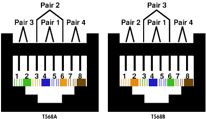
Ethernet Cable Wiring on Well Rj45 Receptacle Wiring For Both Standards Are Shown Below
Well Rj45 Receptacle Wiring For Both Standards Are Shown Below.


Ethernet Cable Wiring on Ethernet Cables  By Karl Shoemaker  Ak2o
Ethernet Cables By Karl Shoemaker Ak2o.


Ethernet Cable Wiring on Cat 5e Wiring Diagram
Cat 5e Wiring Diagram.


Ethernet Cable Wiring on Rj45 Pinout Wiring  How To Make Up A 10baset 100baset Connection  Eia
Rj45 Pinout Wiring How To Make Up A 10baset 100baset Connection Eia.


Ethernet Cable Wiring on Category 5 Patch Cable In T568b Wiring
Category 5 Patch Cable In T568b Wiring.


[Continue reading...]

Saturday, August 3, 2013

Basic devices in the car audio system

car amplifier
Entertainment in the form of music, news or even movies, generated from a series of audio devices found in a car. The series device known as a car audio system.
What tool or device contained in car audio system?

  • Car Head Unit - Head unit is the core of a car audio system, part of the car audio system that plays sound. The continued development of technology makes the head unit is no longer only serve as a radio receiver FM / AM CD player and a player, some have additional functions to be able to play MP3s. There is also a car head unit that has the ability to play DVDs complete with monitors and can be connected with IPOD.
  • Power Amplifier - The function of the power amplifier is to amplify the signal coming out of the head unit. In the world of various types of car audio power amplifiers are divided into several classes, such as class A, B, AB, and D. Each class power amplifier has the advantage that its usefulness can be tailored to our needs in building a car audio system. In addition to class division, the division of power amplifiers can also be seen from the number of channels (channels) and the amount of power generated by the power amplifier.
  • Speaker - A device that functions convert electronic signals into audible sound. The speakers were divided into several parts / components, namely, subwoofers, woofers, mid-range, and tweeter. In order for speakers to work properly, required a series of electronic components that serves as a filter (cross over).
  • Processor - With advances in technology processors play a significant role in a car system. Inside there is a processor features like time correction, cross-over-active, etc. equalizer. With the functions it will be very easy at the time of tuning car audioaudio system.
[Continue reading...]

Thursday, August 1, 2013

Cable Verifycrossover Cable Configured

Ethernet Wiring on Extra Costs For The Electricity And Telephone Network Voip Wiring
Extra Costs For The Electricity And Telephone Network Voip Wiring.


Ethernet Wiring on Cable To Verify A Crossover Cable Is Configured As Follows
Cable To Verify A Crossover Cable Is Configured As Follows.


Ethernet Wiring on Ethernet Cable Royalty Free Stock Photo
Ethernet Cable Royalty Free Stock Photo.


Ethernet Wiring on Beginnercode Com    Connecting Network Cable Ends
Beginnercode Com Connecting Network Cable Ends.


Ethernet Wiring on 10 Metre Cat5e Rj45 Ethernet Lan Network Cable Lead  10 Meter
10 Metre Cat5e Rj45 Ethernet Lan Network Cable Lead 10 Meter.


Ethernet Wiring on An Ethernet Cable And A Phone Cable
An Ethernet Cable And A Phone Cable.


Ethernet Wiring on Electronics Offers Gpib To Modbus Rtu Interfaces  Modbus Interface
Electronics Offers Gpib To Modbus Rtu Interfaces Modbus Interface.


Ethernet Wiring on Ethernet Cable For Ps3   Sony Playstation   3   Ps3 Slim   Shop By
Ethernet Cable For Ps3 Sony Playstation 3 Ps3 Slim Shop By.


Ethernet Wiring on Find More Network Cable Choices And Information From Comtrad Cables
Find More Network Cable Choices And Information From Comtrad Cables.


Ethernet Wiring on Phone Cable An Ethernet Cable Also Has Eight Wires While A Phone Cable
Phone Cable An Ethernet Cable Also Has Eight Wires While A Phone Cable.


[Continue reading...]
 
Copyright © 2012. Raul's Diagrams Collection - Posts · Comments
Powered by Blogger